

Thermoformed ESD Trays / MC-77226
Thermoformed semiconductor packaging
MC-77226
25-Cavity QFP Storage Tray
A 25-cavity QFP tray with central support features and surrounding relief for a leaded package. Available in black conductive and clear antistatic material.
Does this tray look close to what you need? Send us your device information. Malaster can help review the fit, material choice and requirements for your application.
Discuss This Tray for Your Application
Mention MC-77226 when you contact us.
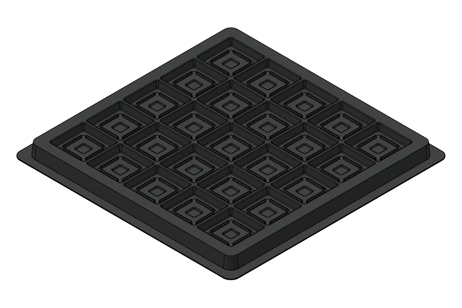
A starting point for your device
The MC-77226 places twenty-five supported pockets in a square 7.250″ × 7.250″ tray. The 1.095″ square cavity reference and the shaped support arrangement should be reviewed together for a QFP device.
Send body size, lead span, lead pitch and the formed lead profile. The body must be supported appropriately while the leads retain the clearance required for your handling and storage process.
If your device differs from the reference application, contact us anyway. We can discuss whether this tray, another existing design or a custom packaging solution is worth exploring.
Tray at a glance
| Tray reference | MC-77226 |
|---|---|
| Cavity layout | 25 supported cavities in a 5 × 5 arrangement |
| Reference application | 84-lead QFP reference design |
| Reference cavity length × width | 1.095″ × 1.095″ Approximately 27.8 × 27.8 mm |
| Reference depth to support level | 0.150″ Approximately 3.8 mm |
| Overall footprint | 7.250″ × 7.250″ Approximately 184.1 × 184.1 mm |
| Reference overall height | 0.403″ Approximately 10.2 mm |
| Material options | Black conductive Clear antistatic |
Use these reference dimensions for an initial size comparison. Actual fit depends on the device profile, pin clearances and selected material. If your device is close to these dimensions, contact us to review the fit.
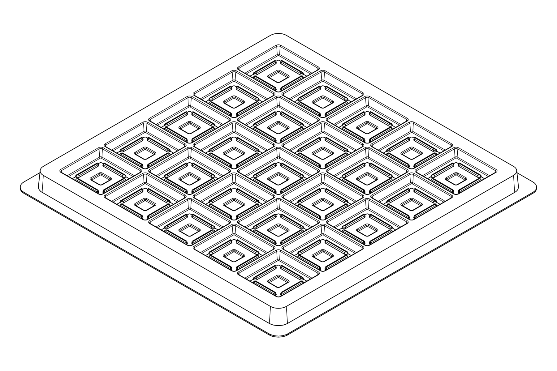
Look beyond the overall size
The line view reveals the nested support and relief features. The 0.150″ reference is to a support level; it should not be read as the depth of every surrounding recess.
Tell us how the tray will be used, whether for work-in-process handling, storage or a shipping application. We can then review the tray as part of the complete packaging requirement.
Choose a material for your application
MC-77226 is available in both black conductive and clear antistatic material. Tell us about your ESD requirements, handling environment and any need to see the device through the tray so we can discuss the appropriate option.
Black conductive
An option for applications requiring conductive tray material. Share your material or ESD specifications so we can review the requirements with you.
Clear antistatic
An option when clear material is useful for viewing the device. We can discuss the antistatic material requirements alongside fit and handling.
Could MC-77226 work for your device?
You do not need a complete specification to begin. Send what you have, and we can help identify the details needed to assess the tray and prepare a quotation.
- A device drawing, photograph, package outline or description
- Any known dimensions, pin clearances or handling concerns
- Your material preference or ESD requirements, if known
- Estimated quantities and timing
Please include MC-77226 in your inquiry so we can refer to this tray design.