
Technical decision guide · Existing, modified, or new
Should You Use an Existing ESD Tray, Modify a Design, or Build a Custom Tray?
When I review a tray request, I do not start by matching a package name to a photograph. I start with the current device drawing, its revision, and the work the tray must do. Similar is not the same when a pocket has to support a component, protect its features, separate loaded trays, and work through the actual handling path.
An existing tray creates two separate questions: can I identify the configuration, and is it still correct for this device, revision, and process? Those questions lead to three distinct paths.
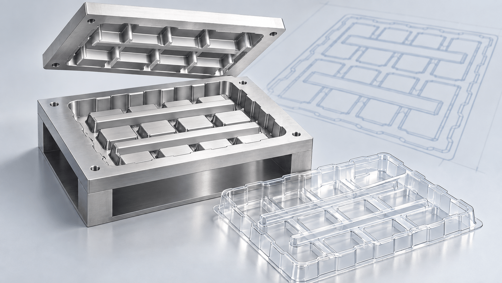
By Mike Cordingley
The Malaster Company, Inc.
Step 01
Identify the actual existing or legacy tray
Start with the strongest evidence available: a Malaster MC number, every molded marking, photographs of both sides of the tray, a photo with the device seated, prior order information, or a physical sample. Those details can identify a candidate design or reveal formed features that a front-view photograph hides.
Then provide the current device drawing and revision. A package family or manufacturer part number is not enough on its own. A device can retain the same family name while its body height, lead profile, underside features, or keep-out requirements change. Those are the details that determine whether a cavity still supports the device correctly.
A useful replacement inquiry answers both sides of the question: what tray do you have or want to replace, and what current device and process must the replacement support?
If the request is for a standardized injection-molded JEDEC matrix tray rather than a Malaster thermoformed design, begin with JEDEC Tray Solutions. A current tray drawing and revision are still required to confirm cavity, material, and stack configuration.
Step 02
Choose the right starting path
The decision is not simply “stock or custom.” It is whether an existing configuration can be identified and verified, whether an existing design gives us a useful engineering starting point, or whether the device and process deserve a clean new cavity design.
Path 1
Existing or legacy Malaster tray
Start here when: there is a specific tray reference and the device and application appear unchanged.
Review: support and clearance, device revision, material, orientation, loaded-tray behavior, and the requested configuration.
Path 2
Existing design as a starting point
Start here when: an existing layout, footprint, nesting arrangement, or cavity concept is close but not proven.
Review: which features remain useful and which need a controlled change to geometry, material, cavity count, access, or handling.
Path 3
New custom tray
Start here when: the component, its protected surfaces, the process, or the package architecture has changed beyond what an existing design can support.
Review: device geometry, support planes, clearances, orientation, extraction, equipment interface, material, and the full packaging system.
Once a path is identified, use the five-check thermoformed tray guide for the detailed fit review: cavity levels, support surfaces, handling, material and thickness, and the loaded assembly.
Step 03
Tooling geometry determines what a controlled change really means
A close existing design can preserve a useful footprint, nesting relationship, packing method, or manufacturing starting point. That does not mean the original tray can simply be called a fit, or that an existing tool can automatically be changed.
| Change under consideration | What it requires |
|---|---|
| Material or starting-sheet option | Review the formed geometry, rigidity, electrical requirements, support, and handling. Starting sheet thickness is not a guaranteed cavity-clearance adjustment. |
| Cavity, support, or clearance change | Review the actual component geometry and the existing tool against the new requirement. A small drawing change can affect the support plane, release, formed-wall distribution, or how trays stack. |
| Count, orientation, footprint, or process change | Review loading, removal, tray pitch, equipment indexing or pickup, cover/stack interaction, and outer packaging as one system. |
Thermoforming does not preserve nominal sheet caliper uniformly across every formed feature. Deep draws and geometry influence material distribution. There is no universal clearance change or tolerance promise that can be made from a material thickness alone.
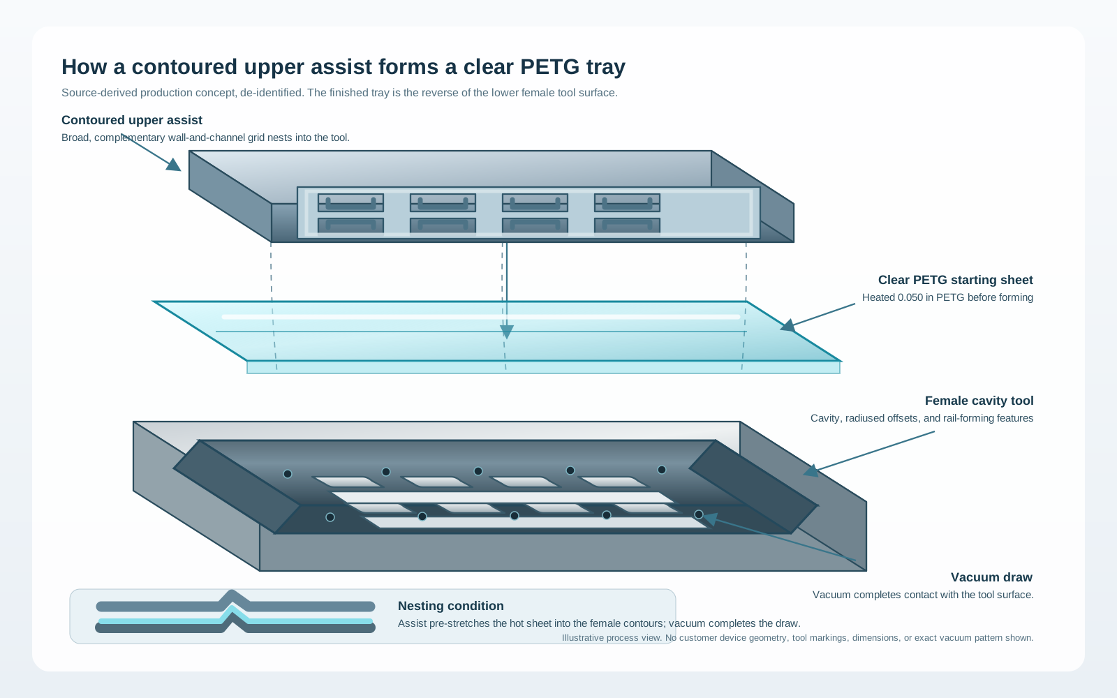
In a female cavity tool, the component-facing inside surface is formed against the tool cavity. That can be useful when the cavity geometry must be controlled in thicker starting material. It is not a blanket tolerance claim: the opposing surface still responds to material distribution, cooling, and the specific form geometry.
Tool reuse or revision must be evaluated against current tool condition and geometry, the proposed change, the selected material, and the production requirement. Sometimes an existing design provides useful learning but a new tool is the cleaner engineering path.
Step 04
Start new when the risk is in the details
A new tray is usually the better starting point when existing designs cannot provide the required support, clearance, orientation, loading access, retention, or equipment interface. The same is true when a device revision introduces features that must stay clear, or when a shipping system changes how loaded trays need to stack or be restrained.
A new custom request should still be specific. The strongest starting point is a current drawing, CAD model, or representative sample plus a description of the application. From there, the review can establish support surfaces, protected areas, allowable movement, cavity orientation, tray count and pitch, material requirements, and the system around the tray.
The Custom Thermoformed Packaging Engineering Handbook covers the deeper cavity, material, tooling, and validation work that follows. It is the right resource once the decision is no longer “which path?” but “how should this tray be engineered?”
Step 05
A customer-directed review that leads to a buildable solution
The component owner defines what must be protected, which surfaces may be contacted, the required ESD and material performance, and how the package moves through the process. My role is to turn those requirements into a tray path that can be reviewed before tooling or production is released.
1 · Trace
Establish the real starting point
Review tray markings, prior orders, samples, photos, and what is known about the current device and handling path.
2 · Define
Translate requirements into geometry
Set support points, keep-outs, orientation, access, tray count, stack behavior, material, and equipment or packaging interfaces.
3 · Review
Give the customer something specific to approve
For new or changed work, I develop the tray model or drawing used for technical review, quotation, tooling decisions, and production planning.
4 · Produce
Build around the approved configuration
The scope can include tooling, vacuum forming, press work, assembly or kitting, quality checks, and shipment preparation.
This is why a tray review is more useful than a quick catalog guess. It puts fit, process, material, and production requirements on the same record before the project advances.
Step 06
Specify the material and the full package, not the color
Material affects electrical behavior, visibility, rigidity, and formed geometry. Black conductive and clear antistatic are useful descriptions of available options, but color is not a material specification or a test report. The relevant requirement should state the electrical properties, test method or customer specification, and the use environment.
For applications governed by a defined ESD control program, include that requirement in the review. ANSI/ESD S541-2026 describes packaging properties and evaluation for ESD-sensitive items across production, transport, and storage. A tray material alone does not establish the performance of the full shipping package.
Review the tray as part of the complete arrangement: the component, tray, cover or mating tray, stack, restraint, and outer ESD enclosure or carton. An open tray that looks correct on the bench may need a different approach once it is loaded and subjected to the real handling or shipment path.
What to send
Information that lets me make the call quickly
- Current device information: drawing and revision, CAD, sample, or clear photographs including the side and underside.
- Existing-tray evidence: Malaster MC number, molded markings, prior order reference, tray photographs, or a physical sample.
- Contact restrictions: surfaces that may support the device and features that must stay clear.
- Process: how the component is loaded, removed, oriented, inspected, stacked, stored, shipped, or handled by equipment.
- Material and ESD requirements: customer or internal specifications, visibility, cleanliness, temperature, or other defined conditions.
- Packaging system and timing: cover or mating tray, stack count, outer packaging, expected demand, approval path, and target date.
When fit or process performance is uncertain, evaluate the proposed configuration with representative components and the intended handling method. Record the tray reference, material, and configuration that were actually reviewed.
Questions buyers ask
Common questions about existing and custom ESD trays
Can Malaster replace a tray from a photo?
A clear photo can help identify a candidate design, especially with molded markings and a view of the component seated in the cavity. It is not enough to approve compatibility. We still need current component information and the handling requirements.
Can a different material thickness make a tray fit?
Sometimes a different material or starting-sheet option is worth evaluating. The formed result depends on the tool, material, and geometry, so it needs to be reviewed with the component and the intended handling and stacking conditions.
Does a prior order prove the replacement is still correct?
No. A prior order is valuable history, but the device revision, material, tray configuration, handling process, and packaging system may have changed. Confirm what is current before repeating the arrangement.