

Technical guide · Five checks
How to Choose a Thermoformed Tray for Electronic Components
A component can fit inside a tray and still rest on the wrong surfaces. Check support, clearance, and handling before choosing a design.
By Mike Cordingley
The Malaster Company, Inc.
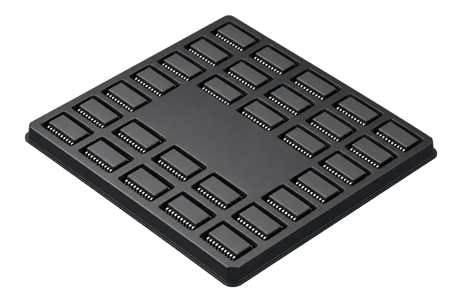
When I review a tray for a customer, I start with the device drawing and the job the tray needs to do. Length and width narrow the search. The underside of the component, its seating position, the material, and the handling process tell me whether a design is worth evaluating further.
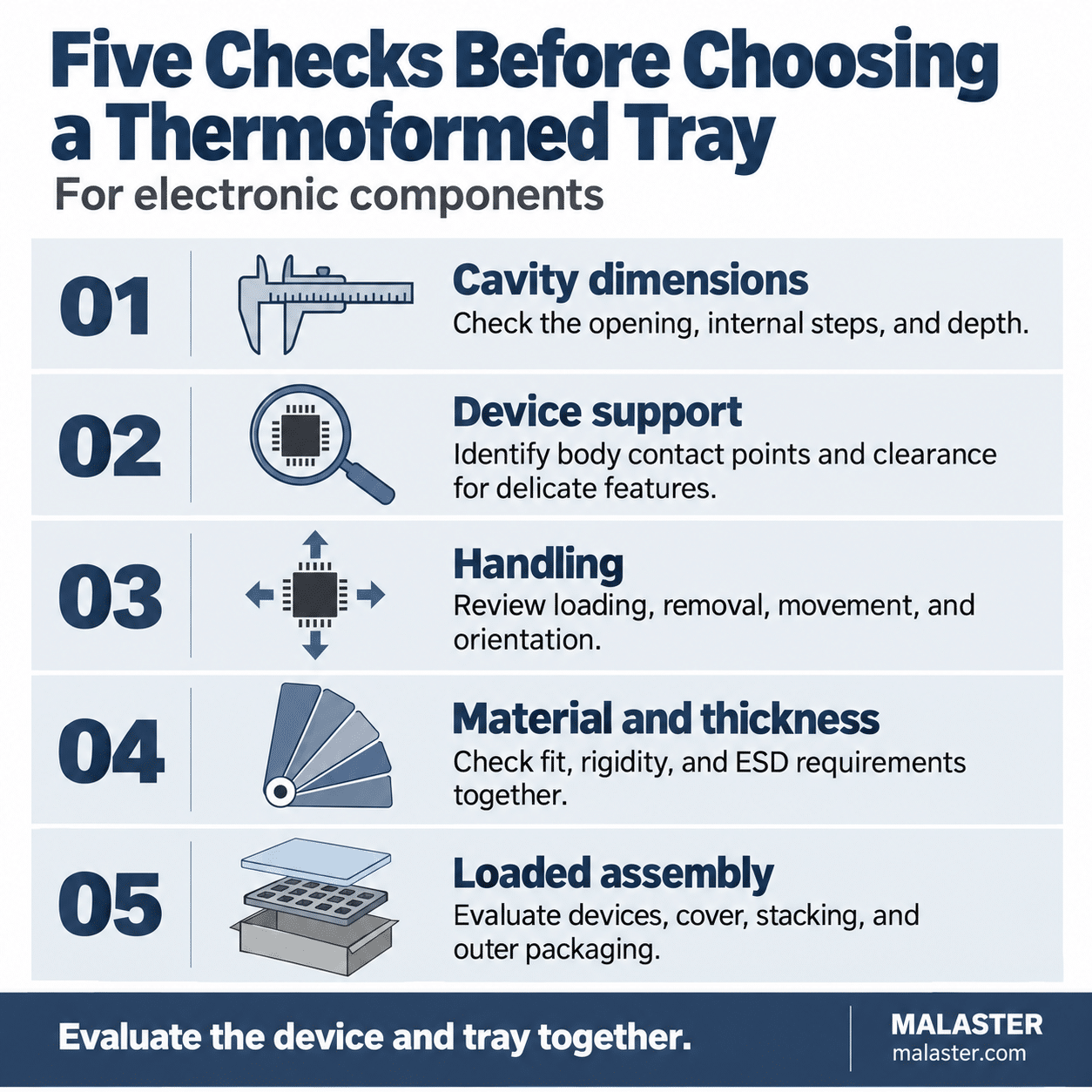
The five checks below explain how to choose a thermoformed tray, starting with a review of Malaster’s existing thermoformed tray designs. They also help identify when a material change is worth exploring or when the device needs a custom design.
Check 01
Read the cavity dimensions at the correct level
Before comparing sizes, establish what each dimension measures. A formed pocket may have a wide opening, a narrower inner profile, a support ledge, and a relief area below the component. The available space changes with depth.
The same care applies to the device drawing. Body width, overall lead span, and the space between leads describe different features. Overall tray height, pocket depth, and depth to a support ledge are also different measurements.
Example: a 32-lead SOJ package and MC-77034
The MC-77034 SOJ tray has stepped rectangular cavities. SOJ leads curve under the package body, making the end view particularly useful when reviewing the seating position and lead clearance.
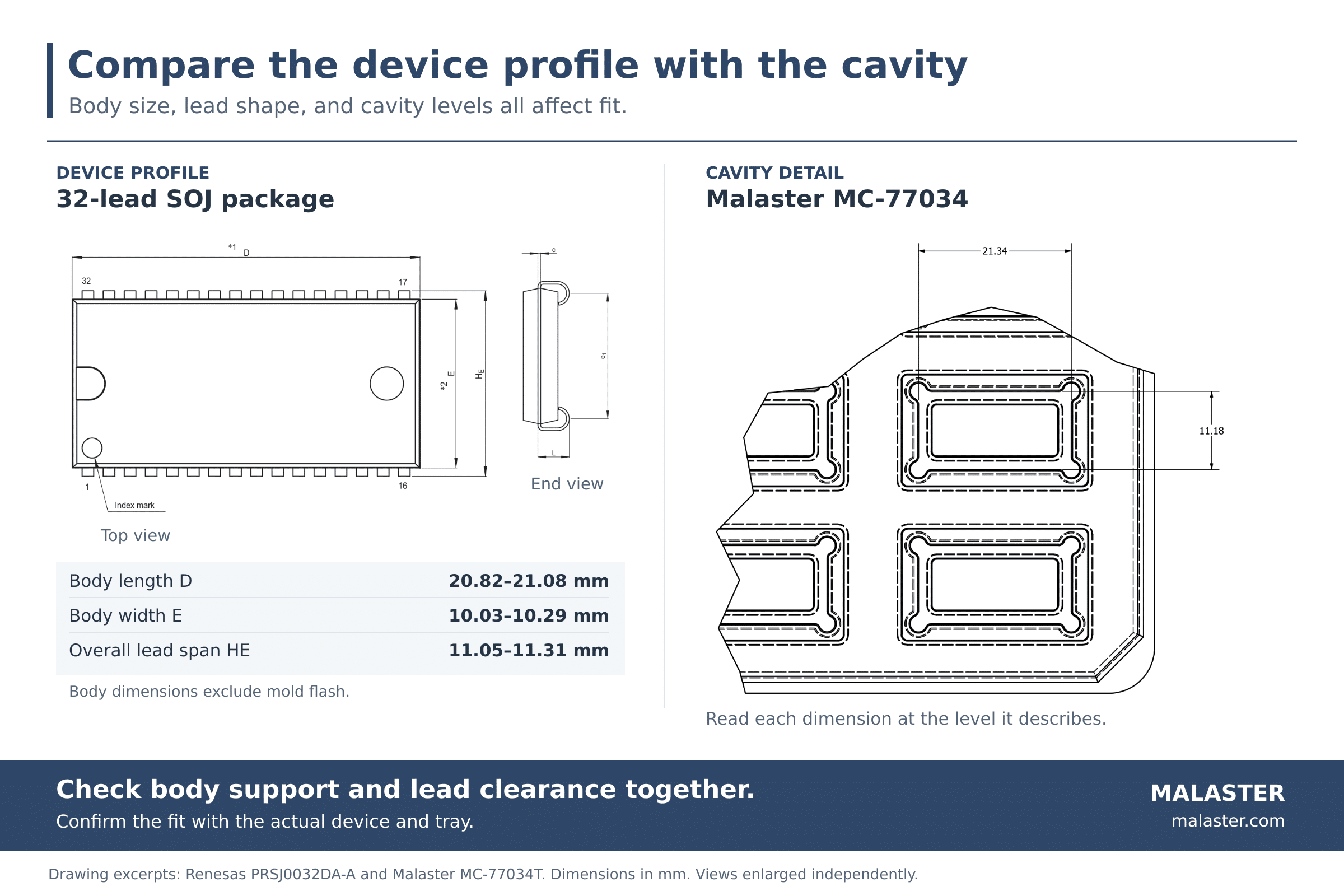
In the Renesas PRSJ0032DA-A package drawing, body width E ranges from 10.03 to 10.29 mm, while overall lead span HE ranges from 11.05 to 11.31 mm. The MC-77034 detail identifies a 21.34 × 11.18 mm span at the indicated cavity level. Those references must be read with the profiles that define them.
A similar number on each drawing does not establish fit. Trace where the body will sit, where the leads extend, and which tray surfaces are above or below them. A section view is needed to resolve the seating depth and vertical clearance.
Review the device’s dimensional limits along with the applicable tray tolerances and proposed material. A sample that fits comfortably does not, by itself, show how a device at the other end of its tolerance range will fit.
Check 02
Identify where the component will be supported
Follow the contact between the component and the tray. Which surfaces carry its weight? Which features could touch when it moves? Which areas must remain clear?
Depending on the device, protected features may include leads, pins, solder balls, connectors, optical surfaces, coatings, or printed identification. A pocket can accept the outside shape while placing a load on a feature that needs protection.
The MC-77139 TO-66 tray shows a different support requirement. The CAD assembly places 15 flanged packages in three rows of five. Reviewing a candidate device means checking where the flange seats, how the body sits in the formed profile, and how far the leads extend below it. The section view makes the lead-to-tray relationship visible. Compare the device’s dimensional limits with the actual tray before approving the fit.
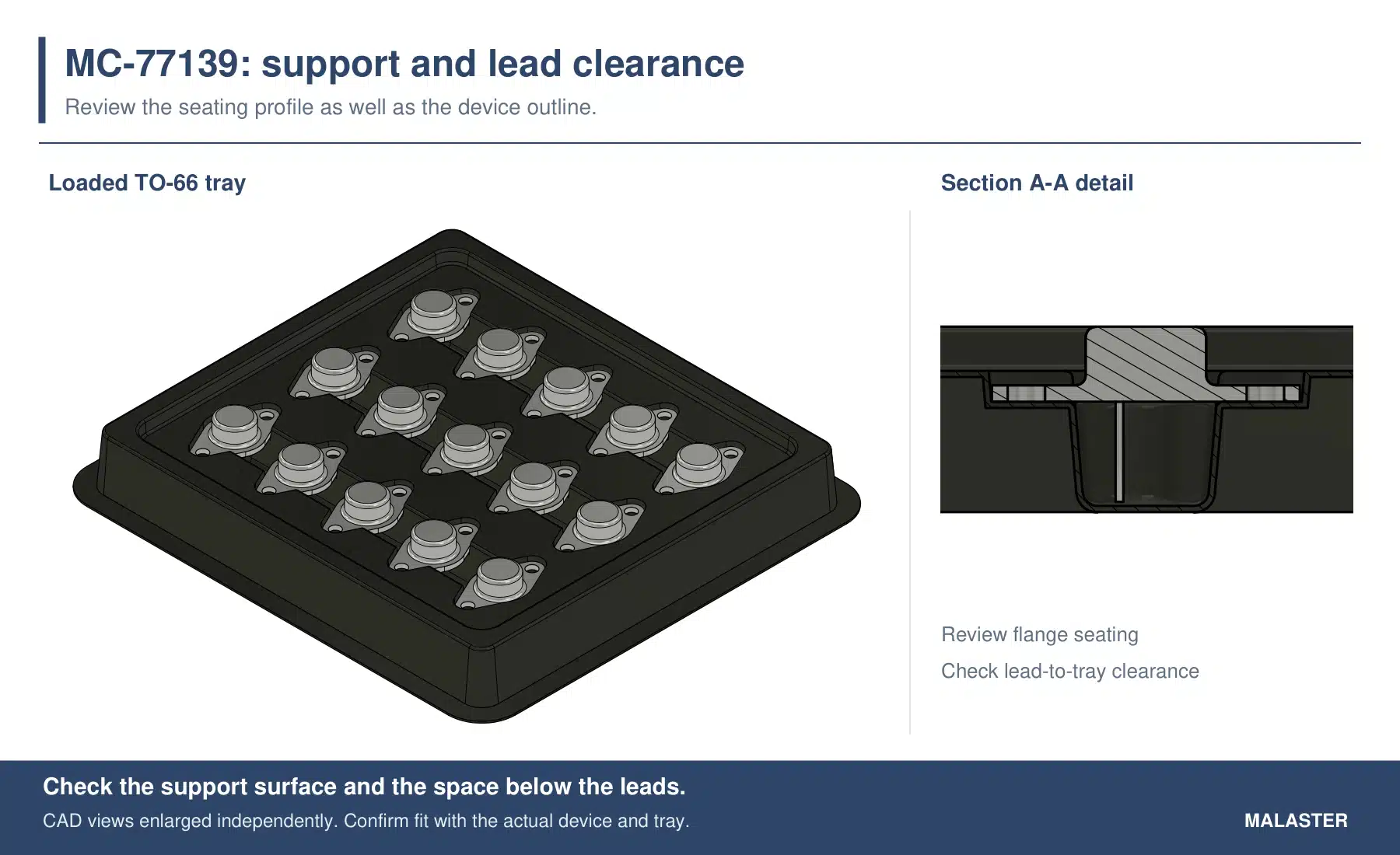
Also consider what happens if the device shifts or tilts. Some movement may be acceptable, provided it stays within the space that protects the component. There is no single clearance value that suits every package.
Check 03
Check loading, removal, and orientation
The tray has to work for the person or equipment using it. Review how the component enters the cavity and comes back out, including the gloves, fingers, vacuum pickup, or other approved tools involved.
- Loading: can the component reach its intended seating position without binding, scraping, or pressure on sensitive features?
- Removal: is there enough access to lift it without prying against leads or dragging a protected surface?
- Movement: can it slide, rotate, or tilt into a contact point that could cause damage?
- Orientation: can the operator place it correctly, and will it remain in that orientation during normal handling?
A close fit can look reassuring until someone has to remove the part fifty times in a shift. Extra clearance can make loading easier, but it still needs to keep movement within acceptable limits.
During a sample review, check positions across the tray using the intended handling method. For automated loading or pickup, also review cavity spacing, pickup position, tray orientation, and the equipment interface. A matching outside footprint is only one part of that review.
Check 04
Review material and thickness as part of the fit
Material selection affects electrical behavior, visibility, rigidity, and formed geometry. It can also make a useful difference when a device is close to fitting an existing design.
Those values describe the starting sheet thickness. The finished walls do not all retain that thickness, and the change does not produce a fixed increase in cavity clearance. The result depends on the tool geometry, material, and forming behavior.
A thickness change may also involve a different material. Recheck fit, support, handling, stacking, and electrical requirements for the proposed configuration. If cleanliness, temperature exposure, or visibility matters to the application, include those requirements in the review.
Choose the electrical properties for the application
Malaster’s catalog includes black conductive and clear antistatic options. Use the exact material’s properties and supporting documentation to evaluate suitability. Color and appearance do not establish its electrical performance.
The EOS/ESD Association’s packaging guidance calls for low-charging, conductive or dissipative packaging within an ESD protected area, with additional discharge shielding outside it. Review the complete packaging arrangement for the environment in which it will be used. A conductive tray’s material description alone does not establish that the loaded package provides discharge shielding.
For a deeper discussion of materials, forming, and tooling, see the Custom Thermoformed Packaging Engineering Handbook.
Check 05
Evaluate the tray as a loaded assembly
A component may sit correctly in an open tray and encounter a problem when a cover, mating tray, restraint, or outer package is added. Evaluate the configuration in which it will actually be stored, moved, or shipped.
The MC-77139 assembly adds a lid over the loaded TO-66 devices. Use the section view to review where the lid may contact the device, how the flange remains seated, and whether the leads stay clear when the assembly is closed. A lid can limit movement, but that restraint must not create an unacceptable load on the component.
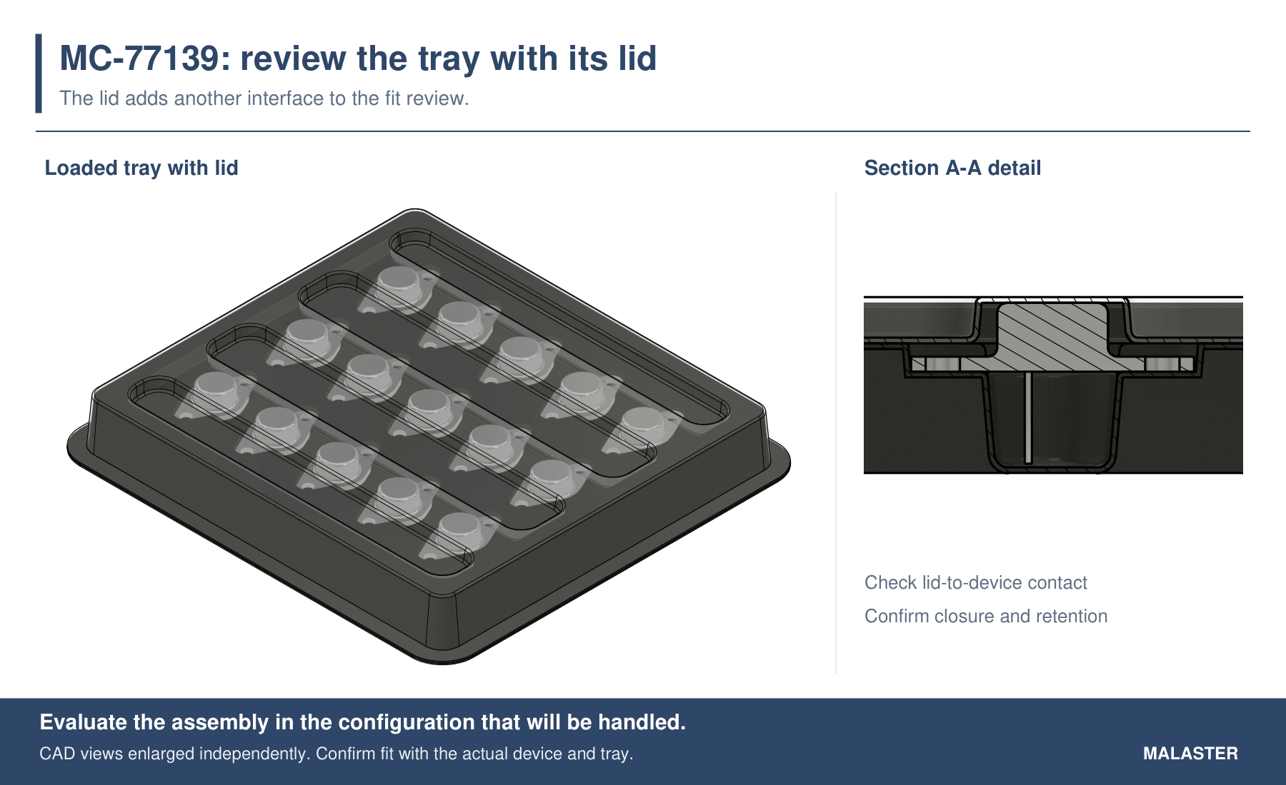
- Upper clearance: does the cover or tray above remain clear of sensitive surfaces?
- Stack compatibility: do the intended trays engage and align correctly when loaded?
- Retention: does the closure control movement without bowing the tray or pressing on the device?
- Outer packaging: are the cushioning, restraint, and ESD enclosure appropriate for the handling or shipping route?
Empty-tray nesting does not establish loaded-tray stacking clearance. A tray that works for internal work-in-process handling may also need additional protection for shipment.
Evaluate the selected material with representative devices and the intended cover or stack before approving the configuration. Shipping applications may require package testing against the customer’s transport requirements. The five checks before shipping electronic components cover the surrounding package in more detail.
Use an existing design or request a custom tray?
Start with existing designs that appear to offer suitable support, clearance, and a useful handling format. The package name in the catalog is a starting point. Similar device geometry may make a design worth reviewing even when its original application was different.
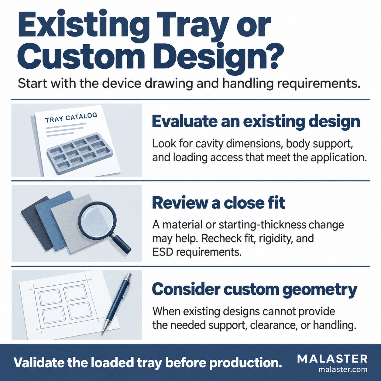
A close dimensional match is worth discussing when the support surfaces are in the right places. A material or thickness option may help, subject to evaluating the revised tray. Confirm the proposed configuration, availability, quantity, and timing once a candidate looks promising.
Custom geometry deserves consideration when existing designs cannot provide the required support, clearance, loading access, orientation, or equipment interface. I would rather identify those limitations during the review than have you discover them while loading parts.
How to choose a thermoformed tray: a final checklist
Use the drawing review to narrow the choices, then check the proposed tray with representative devices. Load and remove them using the intended method, inspect the contact points, and evaluate the cover or stack. Record the tray design, material, and configuration that were actually reviewed.
If the device, material, or handling process changes later, revisit the parts of the fit review affected by that change.
What to send for a thermoformed tray fit review
You do not need to have every detail settled. A short list of likely tray numbers and a clear device drawing are enough to start. Send what you have, particularly:
- The device: a dimensioned drawing, CAD model, sample, or clear photographs, including the underside and side profile.
- The candidate tray: the Malaster part number or the existing packaging you are trying to replace.
- The contact restrictions: surfaces that may support the part and features that must remain clear.
- The process: loading and removal method, orientation, stacking, storage, shipping, and equipment constraints.
- The material requirements: electrical properties, cleanliness, visibility, temperature exposure, or other defined specifications.
- The quantities and timing: evaluation quantity, expected recurring demand, and required date.
These details help determine whether an existing configuration is suitable for evaluation, a material change is worth testing, or a custom tray is the better starting point.
Common thermoformed tray selection questions
Can I choose a tray using only cavity length and width?
Use those dimensions to narrow the options, then review the seating level, device underside, support surfaces, and clearances. Stepped cavities and projecting features require more than an outside-size comparison.
Can changing material thickness make an existing tray fit?
Sometimes. A different starting sheet thickness can change usable clearance within an existing design. The result depends on the tool, material, and formed geometry, so the proposed configuration needs to be evaluated with the device.
Does a matching tray footprint mean it will work with my equipment?
No. Equipment may also depend on tray height, cavity spacing, pickup position, orientation, flatness, and stack behavior. Review the relevant interfaces before approving the tray.
Technical references
The fit-review approach and material-thickness example reflect my packaging application experience. The SOJ comparison uses the Renesas package drawing and Malaster MC-77034T drawing detail shown above. The TO-66 figures use Malaster MC-77139T CAD assembly and section views, with and without the lid. Final selection depends on the actual device, tray configuration, and application requirements.
- Renesas PRSJ0032DA-A package drawing (PDF): 32-lead SOJ package geometry and dimensional limits.
- MC-77034 SOJ tray: design context and stepped cavity geometry.
- Malaster MC-77139T CAD assembly and Section A-A views: TO-66 device seating, lead clearance, and the tray-and-lid arrangement shown in this article.
- Malaster thermoformed packaging handbook: materials, cavity geometry, tooling, handling, and validation.
- EOS/ESD Fundamentals, Part 3: packaging requirements inside and outside an ESD protected area.