

MC’s Engineering Notebook · IC tube accessories
IC Tube Pins, Plugs and Fillers: Retaining Devices, Controlling Movement and Protecting Packaging
Cut foam filler can control unused space, separate devices, cushion tube ends against a bag and serve as a carrier for unusual components. The right pins, plugs and removal tool complete the arrangement.
By Mike Cordingley
The Malaster Company, Inc.
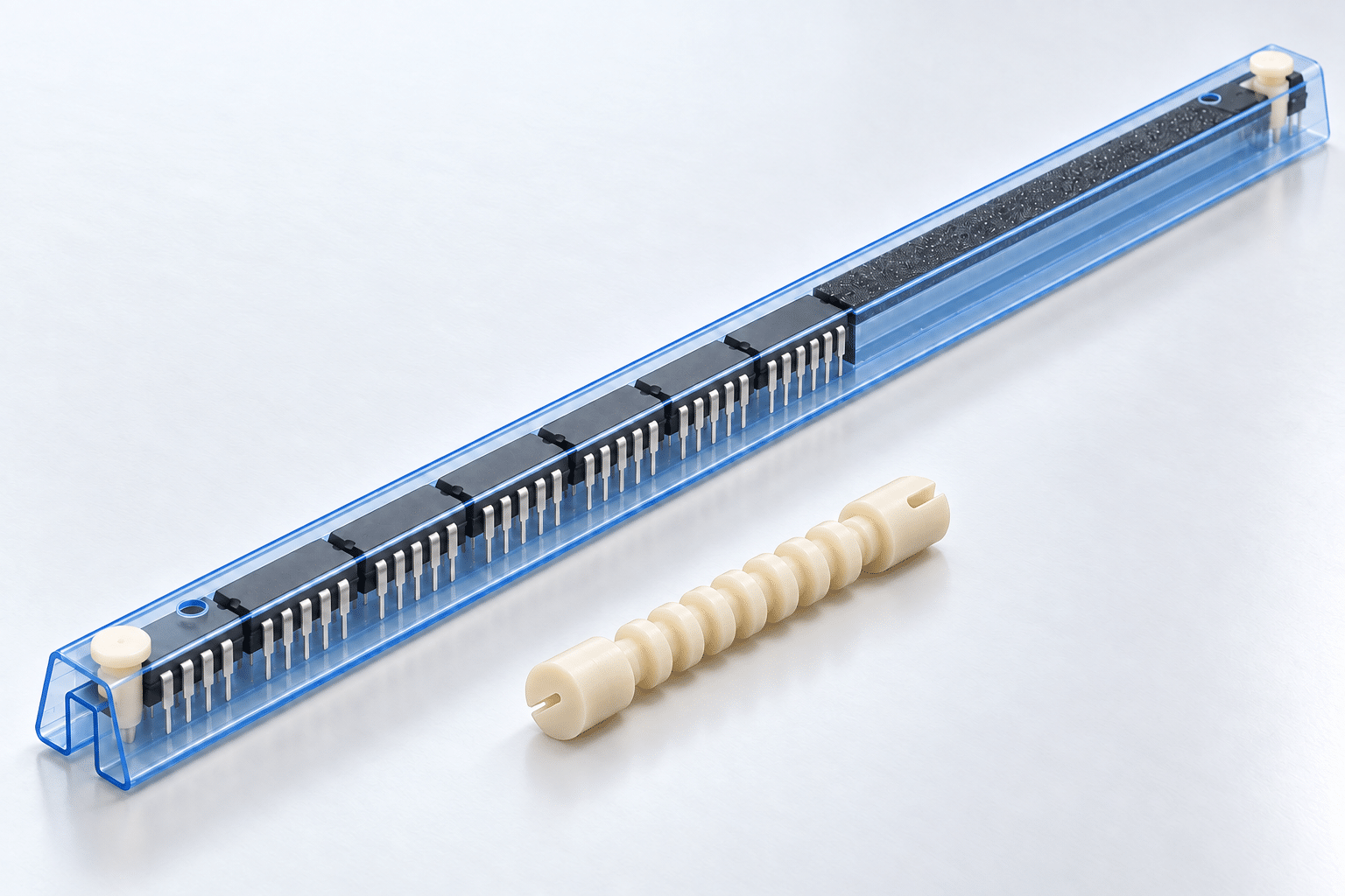
Tube fillers are often treated as something to put in the empty end of a tube. Their usefulness goes further. A strip cut into suitable lengths can cushion individual devices, and a projecting section can help prevent a rigid tube end from poking or slicing through the surrounding bag. In a different loading arrangement, foam can also hold devices by their pins and act as a carrier inside a stock tube.
When I look at a tube assembly, I start with where the device is supported and what can contact it. Malaster’s antistatic IC shipping tubes provide the starting profile. Some devices ride directly on the tube’s support surfaces; others need a suitable foam carrier. Pins and plugs retain the contents, fillers control space and contact, and the MC-1000 pin puller helps with opening a pinned tube.
Start with the tube, then choose its closure
Choose the tube profile for the device body, leads or terminals, and loading orientation. Then select accessories for that profile. A foam carrier can adapt how a device is supported inside a stock tube, provided the tube has enough clearance for the complete assembly. It cannot compensate for interference or insufficient space.
End stop pins
IC tube end stop pins engage prepared holes to retain the contents. Pin shape, hole geometry, wall thickness and surrounding clearance determine the fit. Hole position also affects usable loading length.
The installed pin should retain the load without interfering with leads or fragile features, and its head needs to remain accessible for removal.
End stop plugs
IC tube end stop plugs fit into a matched tube opening. Use the tube part number and profile drawing to identify the plug. A nominal package width or a similar-looking opening does not establish compatibility.
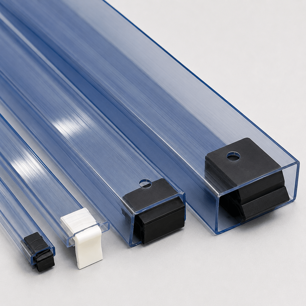
- Profile and engagement: The plug should seat securely without spreading or distorting the tube.
- Insertion depth: Allow for the portion inside the tube when setting device quantity and filler length. Keep the closure clear of leads and fragile package surfaces.
- Handling: The plug needs to stay seated through the intended process and remain accessible for controlled removal.
Pins and plugs may be alternative closures, depending on the tube. Either can retain a load that still has room to move lengthwise. That remaining space is the filler’s job.
Four useful applications for IC tube fillers
Tube fillers, also called tube stuffers, have four practical uses: occupying unused length, separating devices, cushioning the tube ends and carrying devices that need additional support. The contact points and loading arrangement differ with each use.
For the saddle-supported DIP examples below, keep foam clear of the leads.
In the DIP profiles illustrated here, the raised inner saddle supports the device body, with lead channels on either side. The foam rides on top of that saddle and contacts the ends of the device bodies. It must not extend down into the lead channels.
Choose a width and thickness that keep the strip seated at body level. An end view helps show whether the foam stays on the saddle and leaves both lead rows clear.
1. Control the unused space in a partial load
After inspection, sampling or production use, a tube may hold fewer devices than it originally carried. Cut a suitable filler to the remaining usable space between the device stack and the seated closure. The closure should seat normally without forcing the devices together.
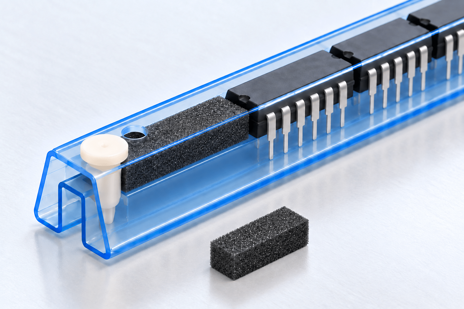
Malaster’s standard listed filler strips are supplied in 19-inch lengths. Cut the working length for the actual tube, device quantity and closures, then check one loaded assembly before repeating the cut for a batch.
2. Place cushions between individual devices
Cut foam sections can provide additional protection where neighboring package bodies would otherwise contact each other.
The MC-600LAS example below holds 600-mil ceramic DIP devices. Each cushion is approximately one-third of the device body length, measured along the tube. This gives the cushion enough length to help it stay seated; very short pieces can shift out of position more easily.
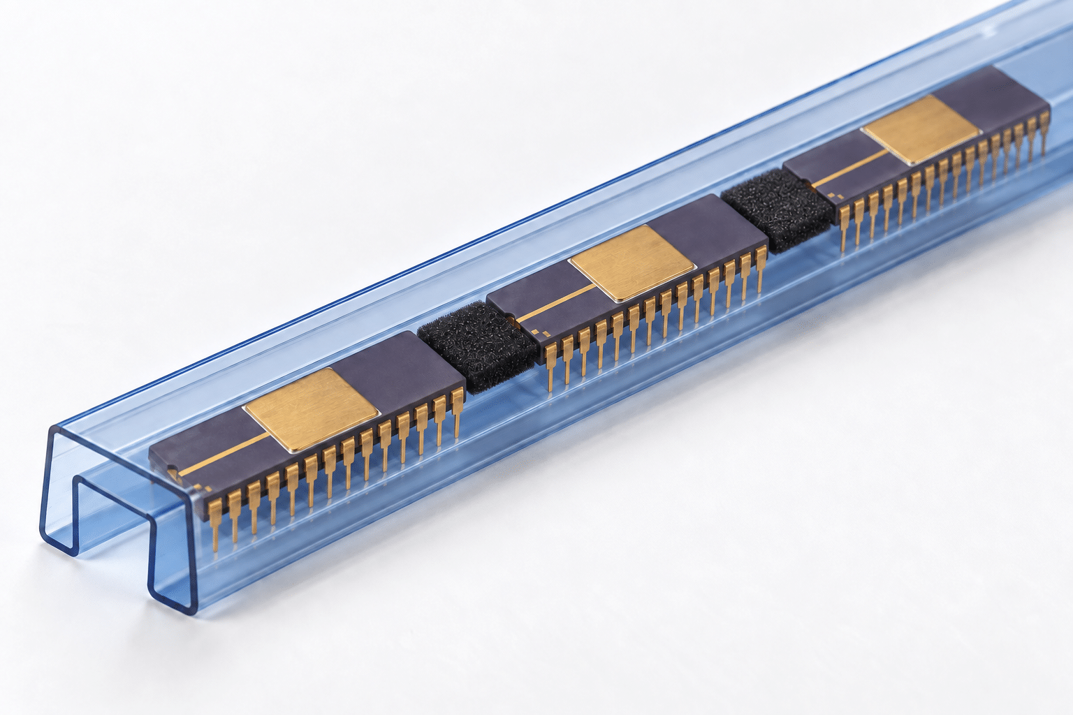
That proportion applies to this example. Other devices and profiles may need different cushion dimensions. Allow for the length and combined compression of the separators when setting device quantity, and plan to remove and account for them during unloading or before automated feeding.
3. Help protect the bag from the tube ends
A rigid tube end can poke or slice the bag even when the devices inside are properly retained. Leaving foam projecting beyond the tube gives the bag a cushioned contact point.
A typical arrangement uses approximately 1/2 inch of projection at each end, with enough foam supported inside to keep it in position. The closure must still retain the contents.
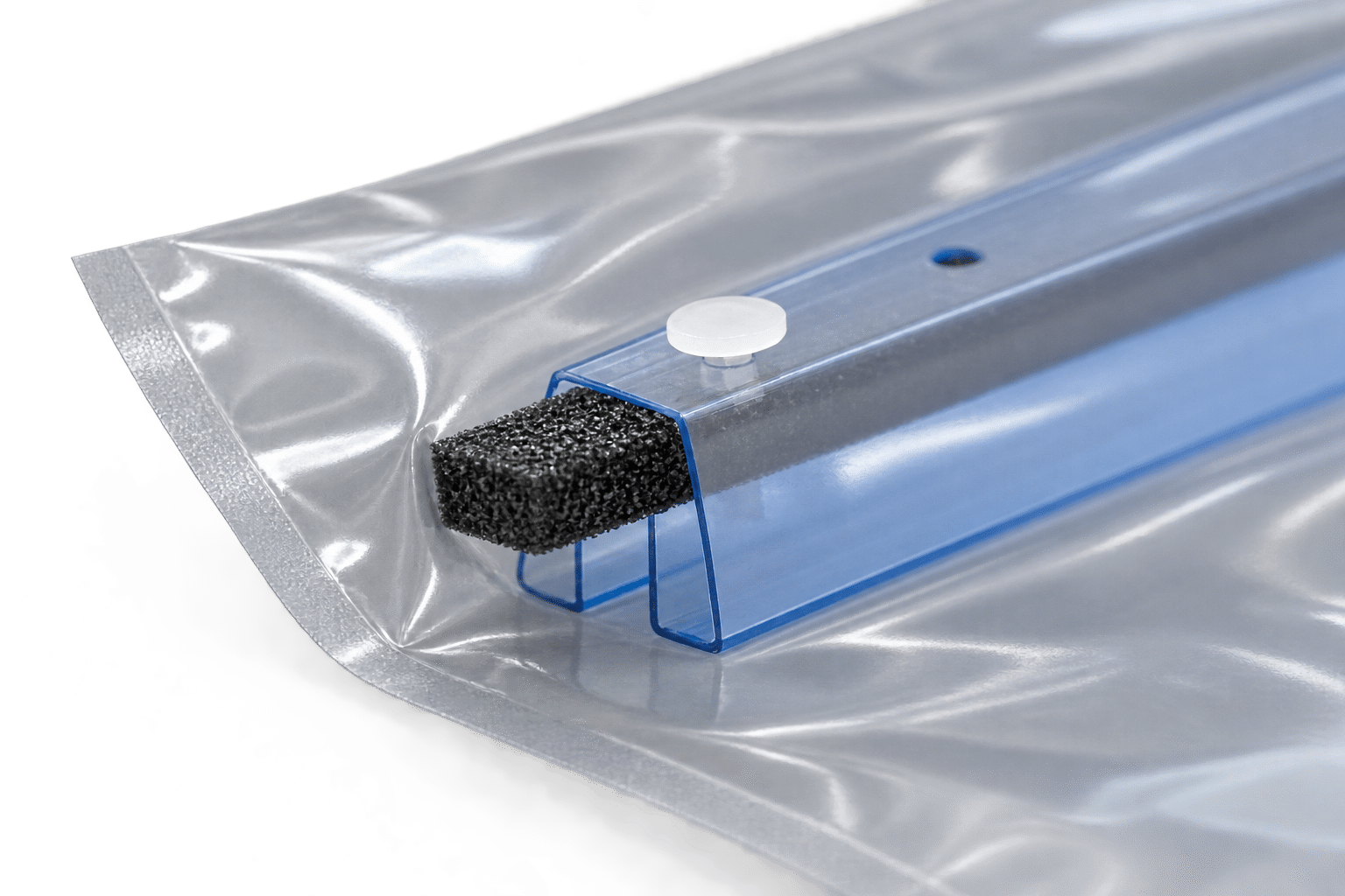
Check both ends in the actual bag. Folds and changes in tube orientation can expose other contact points, so the foam needs to cushion the edges that would otherwise bear against the packaging.
Malaster’s 2-inch RCP pieces
Malaster supplies 2-inch pieces called RCP specifically for tube-end protection. They are available by inquiry and are not currently listed online. Two inches is the supplied piece length; approximately 1/2 inch describes the typical projection beyond the tube.
Ask about RCP or a cut-filler arrangement with the tube profile, closure details and a photograph of the bag contact. Cushioning protects the bag mechanically; its ESD and moisture-barrier properties remain separate selection requirements.
4. Use foam as a device carrier inside a stock tube
Some components have a body shape or pin arrangement that a stock tube cannot support on its own. A suitable closed-cell foam strip can provide the missing support, allowing an existing tube to accommodate a device that would otherwise need a different packaging approach.
The device pins are inserted into the foam, with the components spaced along the strip. The loaded strip then goes into the tube, and compatible end closures retain the assembly. Here, the filler acts as a device carrier: it holds and positions the individual components while the tube provides the surrounding enclosure.
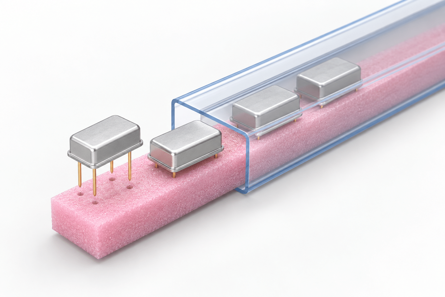
In one application, I considered trays and foam trays before proposing a foam carrier inside a stock tube. The question was whether the foam could hold the devices in the required position while the tube provided clearance around their bodies.
The illustration uses pink closed-cell foam. A suitable conductive foam can also be considered when the application calls for it. Select the material for direct contact with the device pins, including its electrical properties and cleanliness requirements.
Unlike the saddle-supported DIP arrangement, this application deliberately places the pins into foam. Check insertion depth, foam thickness, retention, and body and pin clearance in a sample assembly with actual devices. Confirm that insertion and removal do not bend the pins. The loading and unloading process must suit a foam carrier; devices held this way will not slide freely from the tube.
Choose the filler material for the job
Flexible solid plastic and compressible foam behave differently. Select the material as well as the dimensions.
| Family | Material | Selection consideration |
|---|---|---|
| NTS | Permanent antistatic LDPE; flexible solid plastic | A thin plastic filler or spacer. Listed thicknesses are 0.030 and 0.060 inch. |
| CTS | Black conductive closed-cell foam | A compressible filler where conductive foam is specified. Listed thicknesses include 0.125, 0.187, and 0.250 inch. |
| ASTS | Pink static-dissipative closed-cell foam | A compressible option where static-dissipative foam is specified. Listed thicknesses include 0.125 and 0.250 inch. |
Width and thickness affect seating, clearance and pressure on the load. Electrical properties, cleanliness and device-contact restrictions also matter. Color alone does not establish the electrical classification of a filler or plug.
EOS/ESD Association guidance distinguishes low-charging and conductive or dissipative packaging from the additional discharge shielding needed outside an ESD protected area. An antistatic tube and filler alone do not establish a complete shielding package.
The Malaster filler range provides dimensions and material information. Different widths, thicknesses or cut lengths can be reviewed for the application.
Plan removal with the MC-1000 pin puller
The MC-1000 pin puller, catalog part MC-1000PP, uses slotted ends to engage beneath a compatible pin head. Its ribbed body provides a grip for opening tubes during loading, inspection, unloading or preparation for reuse.
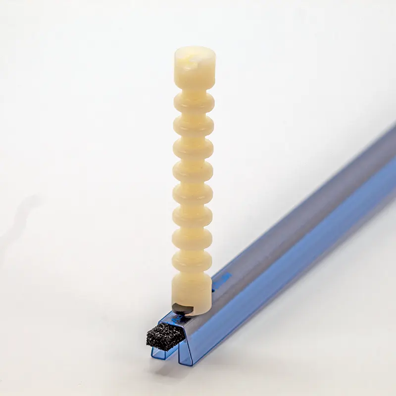
- Check engagement. The slot must reach beneath the pin head with room to work.
- Support the tube and control the contents. Devices may move once the closure is removed.
- Withdraw the pin in its removal direction. Avoid levering against the tube wall or leads. Stop if the pin binds or the tube begins to distort.
Before reuse, inspect the tool slot, pin and retention hole. Damaged pins or enlarged holes can change retention. Use the tool within the application’s established ESD-control process.
Match IC tube pins, plugs and fillers to the device
The saddle-supported DIP examples and the foam carrier illustrate different ways to position a device. Each tube family has its own support surfaces, clearances and closure geometry. Start with the device family, then use the actual device and tube drawings to review the complete assembly.
| AS tube family | What to examine |
|---|---|
| DIP & optoelectronic | Body support and clearance around the two lead rows guide the tube and filler arrangement. |
| SOIC & SOJ | Gull-wing SOIC leads and J-shaped SOJ leads present different contact and clearance requirements. |
| SOP, TSOP & TSSOP | Thin packages require attention to available height, filler thickness, and closure intrusion. |
| PLCC & LCC | Review the actual package: a J-leaded PLCC and a leadless LCC do not have the same contact surfaces. |
| QFN | Body fit, terminal clearance, orientation, and closure geometry still matter for a leadless package. |
| TO packages & socket carriers | Account for the complete shape, including tabs, flanges, projecting leads, and carrier features. |
Listed tube and accessory relationships
These catalog relationships identify parts to consider together. They are accessory options, not a statement that every part is included or required.
| Tube profile | Accessories to review |
|---|---|
| MC-300HAS | MC-300BEP plug; MC-4000WHITE pin; MC-3187CTS foam filler. |
| MC-600LAS | MC-0065-01 plug; MC-4000WHITE pin; MC-6125CTS foam filler; MC-1000PP pin puller. |
| MC-487TSOP/AS | MC-487TSOPBEP plug; MC-4030NTS plastic filler. |
| MC-4QFN/AS | MC-4QFNBEP plug. Review filler selection separately for the device and load. |
Browse the complete antistatic IC tube range to compare profile families and their listed accessories.
Let Malaster review the complete arrangement
Tell me what the packaging needs to solve: movement in a partial load, contact between devices, bag damage, a device that needs additional support or difficulty opening the tube. The following information makes it easier to identify a useful option:
- The tube part number, drawing, or clear photographs of the profile and ends.
- The device drawing or dimensions, including fragile features and areas that must avoid contact.
- The number of devices per tube and how they are loaded and removed.
- Any ESD, material, cleanliness, or production-equipment requirements.
- For bag damage, a photograph of the tube ends and the surrounding package.
Malaster can help identify the tube, match standard accessories, review a foam carrier or custom filler dimensions and supply RCP end protection. A non-stock or custom tube can also be considered when existing profiles do not suit the device.
Have a tube assembly to review?
Share the device, tube, and handling details so the recommendation addresses the complete package.
Discuss Your ApplicationNeed to identify a tube profile? Use the shipping tube inquiry form.