
IC tubes & accessories · Packaging selection and replacement
IC Shipping Tubes: How to Identify the Right Tube When You Don’t Know the Part Number
You do not need the original tube part number to start. If you need suitable packaging for a component, send its current mechanical drawing first. If a replacement must match an existing tube for equipment compatibility or another defined requirement, include the tube’s profile, dimensions, end details, and markings as well.
Need packaging for your component? Send the current device drawing to start a tube selection review.
By Mike Cordingley
President, The Malaster Company, Inc.
Do you need suitable packaging or an exact tube match?
IC shipping tube identification starts by defining the requirement. A tube received with a shipment is not automatically the specification for your next package.
I need packaging for this device
Send first: the current device drawing and how the component will be handled.
Old-tube information: not needed initially when no equipment, specification, or customer requirement ties you to that tube.
I need to replace this specific tube
Send first: the reason a match is necessary, the existing tube information, and the current device drawing.
Review: the profile and the external interfaces, closures, length, and other features that must be preserved.
A manually handled storage application may allow a different profile after review. A tube entering an established feeder may have additional external requirements even when both options can contain the component. State that constraint before comparing replacements.
For packaging selection, send the device drawing first
Send the current mechanical drawing for the actual manufacturer part number, package option, and revision being supplied. A datasheet is useful when it includes the applicable mechanical package outline. An electrical specification page or package-family name alone does not provide that geometry.
Show the complete component, not just its body width
The drawing should establish the body length, width, and height; maximum lead span and lead form where applicable; underside features; and any surfaces that cannot be touched. Include the dimensions and tolerances that define the space the component needs during loading, not only nominal values.
Specify the condition in which the device enters the tube. Trimmed or formed leads, attached hardware, or other assembly details can make a generic package outline an incomplete description. A photograph can clarify the arrangement, but it does not replace missing tolerances.
Explain support, contact restrictions, and handling
Tell me which surfaces may support the component and which must remain clear. Also explain how it will be loaded and removed, whether orientation must be maintained, and whether the tube will be used for storage, shipment, or equipment feeding.
Include customer-defined ESD, cleanliness, temperature, or other packaging requirements. Quantity and timing help establish the practical supply options. They do not determine mechanical fit.
For the broader selection decision, see Choosing the Right Antistatic IC Shipping Tube.
A component fitting inside a tube is not the whole fit check
A suitable tube needs to support the component in the intended orientation while leaving the required clearance around its leads and protected features. Outside dimensions alone do not establish those relationships.
Example: reviewing a 14-lead 300 mil CERDIP
A ceramic dual in-line package, or CERDIP, is one representative device configuration for this type of tube review. The description “300 mil CERDIP” helps identify a family, but does not tell me the complete body and lead geometry or which tube is the best choice.
The example below separates three dimensions that might otherwise all be described as “width”: ceramic body width (E1), shoulder-to-shoulder width (E), and overall lead-row spacing (eB). In the source example, their respective ranges are 0.280–0.296 inch, 0.290–0.325 inch, and 0.325–0.410 inch. These describe different features at different heights, not three ways of measuring the same span.
I compare those features with the tube’s internal support and channels. The review also needs the body length (D), the vertical dimensions, and the lead condition during loading. The practical questions are: where does the body rest, where do the leads sit, and can the component be loaded and removed without interference?
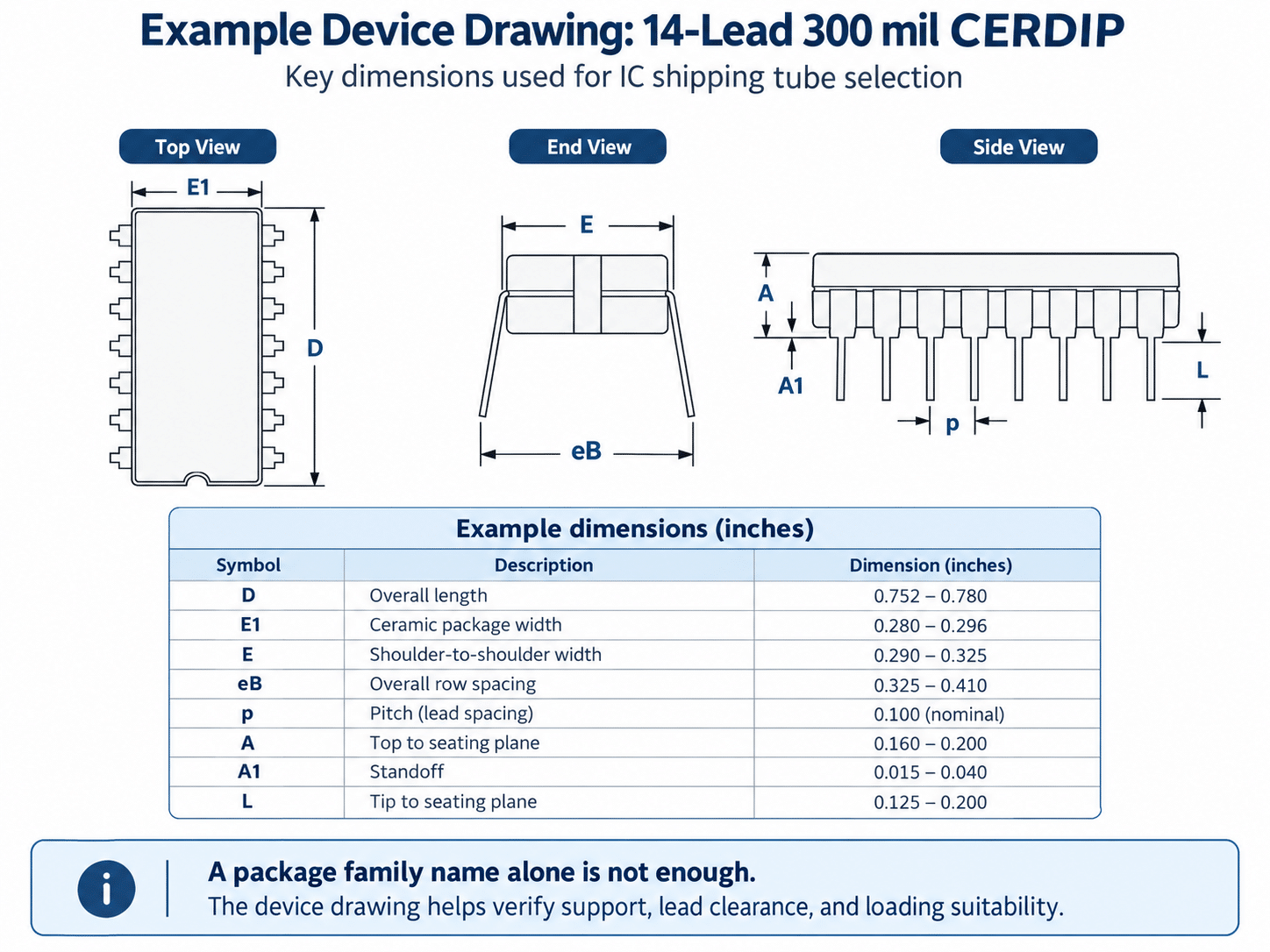
Example dimension source: Microchip Packaging Specification DS00049AA, printed page 9 (2005). The illustrated example omits the window detail. Use the current drawing for the actual device and revision being packaged, not these example dimensions as a universal CERDIP specification.
The old tube may have been workable without being the best option for the next application. Starting with the component drawing allows me to review suitable profiles instead of assuming that the previous packaging must be copied. A different profile may be worth evaluating for support, clearance, or handling; any proposed change still needs a fit and process review.
For this style of leaded device, I review the relationship between the body, internal saddle, and lead-clearance areas. For a leadless device or another package style, the support and restraint questions may be different. There is no single clearance allowance that applies to every component and tube.
The review also needs to account for tolerances. A trial with one nominal sample does not establish fit across the full device and tube dimensional ranges. Where fit or handling is uncertain, evaluate representative parts and the proposed configuration in the intended process.
Browse IC shipping tube families to understand the range. The device drawing and application requirements determine which options should proceed to review.
When you must match an existing tube, document these views
Use this checklist only when the old tube is relevant to a defined replacement requirement. Explain what must stay the same, such as the feeder interface, approved packaging configuration, tube length, closure arrangement, or customer drawing.
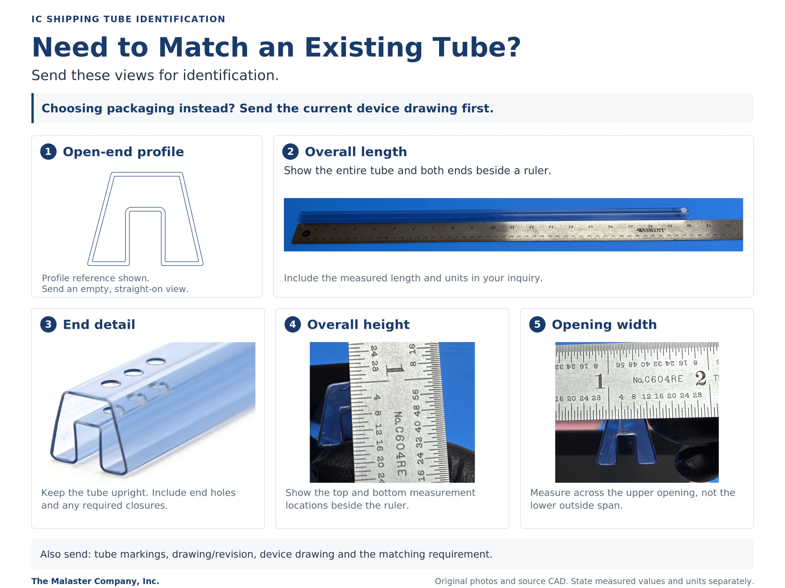
Send any existing tube drawing with its revision. When that is unavailable, these photographs help document the profile and features. Keep the tube upright in a consistent orientation so the views can be compared.
- Straight-on open end. Photograph an empty tube directly into the opening. Show the complete cross-section, including walls, internal support, and channels.
- Overall length. Show both ends beside a readable ruler or tape. State the measured length and units separately.
- End details. Show holes, slots, cutouts, and the end geometry in the same upright orientation. Include separate photographs of the actual installed and removed pin or plug when a closure must be matched.
- Height measurement. Show the ruler or other suitable measuring tool aligned with the top and bottom measurement locations. Avoid an oblique view that hides the endpoints.
- Opening-width measurement. For the profile illustrated below, show the upper loading opening separately from the widest outside span. Record the height where the width was measured and identify the measurement endpoints.
Photograph tube printing, molded markings, and relevant original labels separately. Identify whether a number belongs to the component or to its packaging. Send the complete marking rather than assuming that part of the code identifies the tube.
Keep outside dimensions, opening width, and support geometry separate
“Tube width” is ambiguous unless the measurement location is identified. The widest external span, the internal loading space at a particular height, and the width of an internal channel can describe different features of the same profile.
Mark each measurement on a photograph or sketch. Label the units and distinguish measurements taken from a sample from dimensions and tolerances shown on a controlled drawing. A ruler photograph helps establish scale; it is not a substitute for a readable value or a close-tolerance measurement.
For end holes, distinguish the hole diameter, the distance from the tube end to the hole center, and any center-to-center spacing. Hole-center spacing is not the tube’s overall length. Record the number and arrangement of holes at each end rather than assuming both ends are identical.
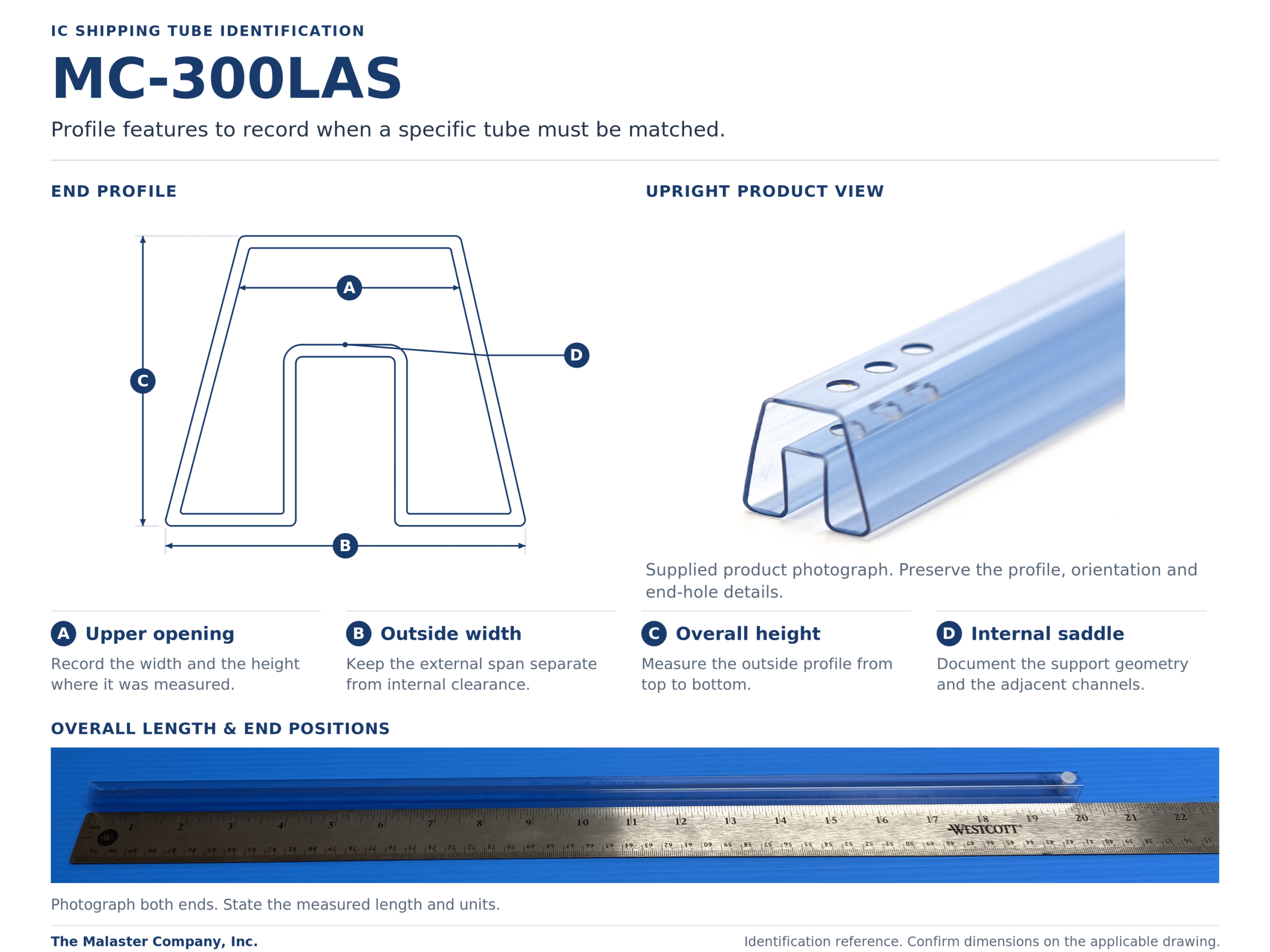
The MC-300LAS reference below separates the upper opening (A), outside width (B), overall height (C), and internal saddle (D). It combines Malaster’s profile linework with original product and measurement photographs. This is an identification reference, not a dimensioned production drawing or a fit recommendation for an unspecified component. Confirm specifications against the applicable current drawing.
Review the material and complete packaging arrangement
Mechanical fit and ESD performance are separate checks. A photograph or material color does not establish an electrical specification. Provide the applicable material documentation or customer requirement rather than treating “antistatic,” “conductive,” and “shielding” as interchangeable descriptions.
The EOS/ESD Association’s packaging guidance distinguishes low-charging and dissipative or conductive properties from the discharge shielding needed outside an ESD protected area. An antistatic tube should not, by itself, be assumed to provide the complete shielding function.
Review the device, tube, compatible end closures, any filler, and outer packaging together. A filler may help manage unused space or provide support in an appropriate arrangement; it does not automatically correct an unsuitable tube profile. The separate guide to IC tube pins, plugs, and fillers explains those applications.
What happens if the original tube cannot be identified or sourced?
An unavailable original part number does not necessarily end the packaging review. First establish which requirements are fixed and whether an alternative may be evaluated.
I can compare the device and application with available profiles, review a non-stock requirement, or discuss a custom option when justified. A different packaging format may be worth considering when a tube does not provide an appropriate support or handling arrangement.
Availability, quantity requirements, lead time, and the approval process must be confirmed for the actual option. A similar appearance is not enough to call a replacement interchangeable or approved for an existing production process.
What to send Malaster for an IC shipping tube review
For packaging selection without an old-tube constraint
- Current device drawing: manufacturer part number, package option, revision, and dimensions with tolerances.
- Application: loading and removal method, orientation, permitted support surfaces, and protected features.
- Requirements: ESD/material specifications, relevant handling or environmental conditions, quantity, and timing.
Choose New Tube Selection in the inquiry form. No old-tube photographs or measurements are needed initially.
For a replacement that must match an existing tube
- Matching requirement: explain which equipment, specification, or customer requirement makes the existing tube relevant.
- Tube evidence: current drawing and revision, or the end-profile, length, end-detail, height, and opening-width views described above; include markings and closure details.
- Device and application: include the current component drawing and identify what has changed, if anything, since the old configuration was used.
Choose Existing Tube Identification or Replacement for Existing Tube in the form. Identify missing information and label any estimates clearly.
Questions about identifying and replacing IC shipping tubes
Can I request a tube without knowing the original part number?
Yes. Start with the current device drawing and intended use. Include existing-tube information only when a particular tube must be matched.
What if I do not have a device drawing?
Contact Malaster with the component identification and information you have. Photographs, measurements, or an available sample may help begin the review. Missing geometry, tolerances, or revision information may still need to be resolved before compatibility can be confirmed.
Does a package name such as DIP, SOIC, or QFN identify the tube?
No. It narrows the family. The actual device dimensions, support and clearance requirements, and handling process determine which profiles should be evaluated.