
Wafer packaging & application engineering
How to Configure Wafer Jar Packaging
Wafer jar packaging works as a coordinated assembly: the jar provides the enclosure, foam provides cushioning and support, and separators keep selected surfaces apart. For conventional round silicon wafers, configure these components around wafer diameter, thickness, quantity, and handling requirements.
The same approach also creates room for customization. Malaster can adapt wafer jars to a wide range of sizes and shapes through custom foam configurations, including square solar wafers, wafers mounted in dicing frames, and wafer-processing blades and tools.
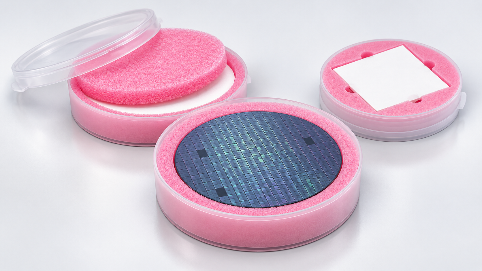
Understand the assembly
What makes up a wafer jar packaging configuration?
A horizontal wafer jar holds wafers in a flat arrangement. A conventional assembly combines a foam sidewall liner, upper and lower cushion discs, and separators at the wafer faces. A separator, also called an interleaf, is a thin layer placed between adjacent parts or surfaces.
Malaster supplies wafer jars and protective foam liners, individual components, and complete configurations. The useful starting point is the part and handling requirement, followed by the available jar dimensions.
Swipe the table horizontally to compare component roles.
| Component | Role in the configuration | What determines the choice? |
|---|---|---|
| Jar and lid | Provide the enclosure and available internal space. | Part envelope, usable diameter or opening, internal depth, and closure. |
| Foam liner or custom insert | A conventional liner cushions the inside vertical perimeter of the jar base. A custom insert can provide a different support arrangement. | Shape, allowed contact, edge clearance, and loading or removal method. |
| Foam cushions | Provide cushioning above, below, or at specified positions within the assembly. | Foam construction, thickness, stack height, and intended compression. |
| Wafer separators | In the illustrated Tyvek arrangement, separate each wafer from the next and separate wafer faces from foam cushions. | Material, outline, thickness, surface compatibility, and the specified layer sequence. |
The component list and quantities depend on the design. A configuration for one part may differ substantially from a multi-wafer stack, and a custom interior may replace the usual liner arrangement.
Conventional round-wafer packaging
How are the wafer jar layers arranged?
In this Tyvek-separated configuration, Tyvek sits between every pair of silicon wafers and between the foam cushions and the wafer faces. The exploded view uses three wafers to make those repeated interfaces visible.
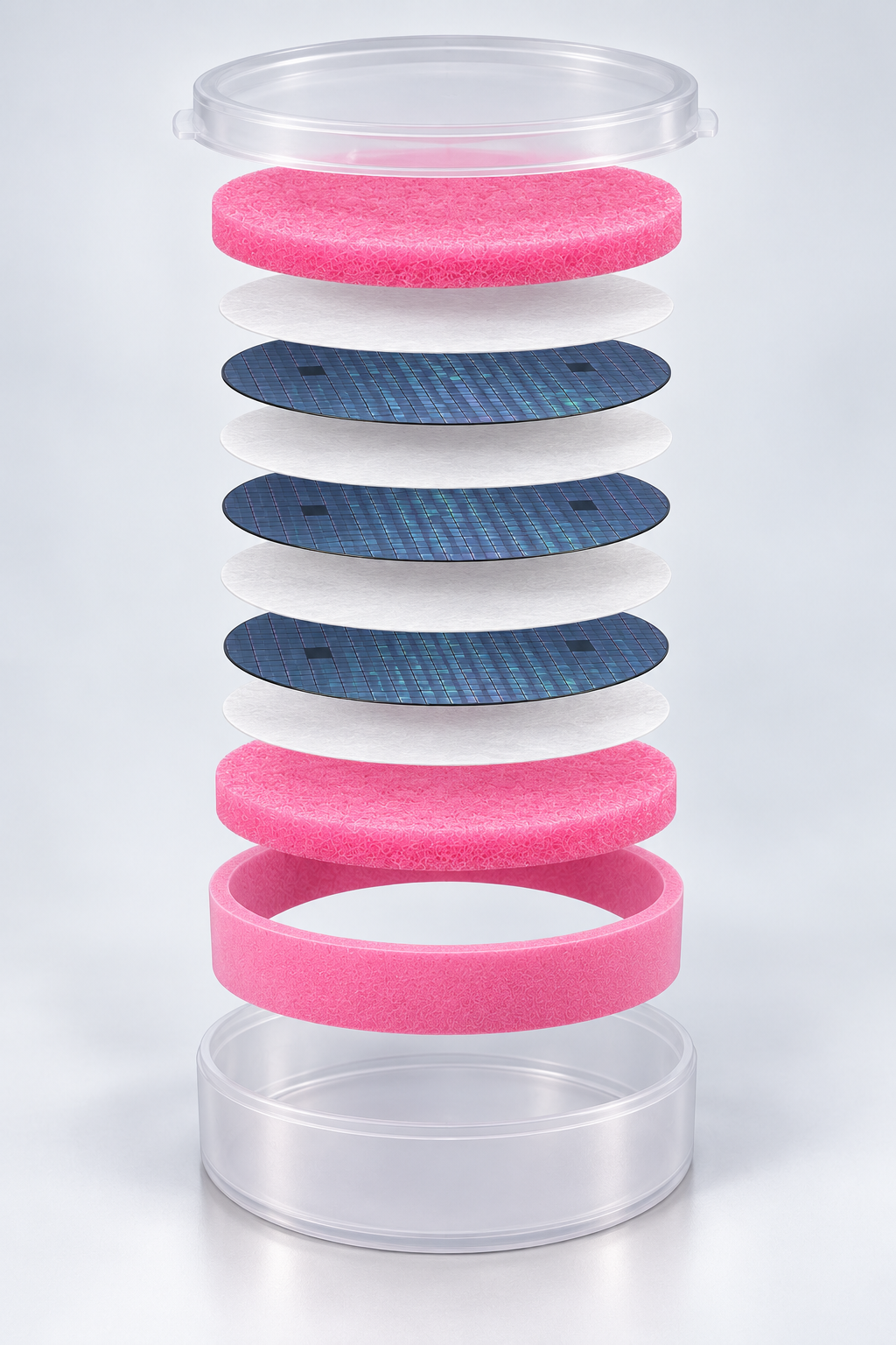
Read the illustration from the base upward
- Jar base. Provides the enclosure for the assembled stack.
- Foam sidewall liner. Fits against the inside vertical wall. It surrounds the stack when assembled; it is not another disc underneath it.
- Lower foam cushion disc. Provides cushioning beneath the wafer stack.
- First Tyvek separator. Separates the lower cushion from the first silicon wafer.
- Wafers with Tyvek between them. Repeat wafer, separator, wafer as required. This illustration contains three wafers.
- Final Tyvek separator and upper cushion. Tyvek covers the last wafer before the upper foam disc is added.
- Jar lid. Closes over the completed assembly at the intended stack height.
One useful arrangement, with quantities defined by the application
Customers have their own internal packaging requirements. Some use fewer wafers with more foam; others use foam and Tyvek between individual wafers. In a Tyvek-separated stack with intermediate foam, retain a Tyvek layer at each foam-to-silicon face interface. The final material list, layer count, and cushion thicknesses follow the customer’s requirements and the available jar space.
Cushioning and support
How do AFD and AFDF foam configurations differ?
AFD is a soft, open-cell antistatic polyurethane foam; AFDF is a firm, closed-cell antistatic polyethylene foam. Their different constructions make foam selection a mechanical decision as well as a material decision. The appropriate choice depends on how the foam must cushion, support, and accommodate the part. [1]
Soft foam cushioning
AFD provides a softer foam option for cushions and fabricated interior components. Its thickness and compression behavior need to be considered with the wafer stack and the available space.
Selection question: Where is compliant cushioning needed, and how much movement or compression can the part tolerate?
Firm foam support
AFDF provides a firmer polyethylene foam option. It can be considered where the interior needs a different support response or custom configuration from the soft AFD arrangement.
Selection question: How should the foam position and support the part while preserving the required clearances?
A change in foam material or thickness changes the way the assembly fits. Select the wafer cushion foam discs together with the jar depth, separator arrangement, and part quantity. For custom work, identify where foam may touch and where contact must be avoided.
The custom foam insert specification guide explains how drawings, contact restrictions, and removal requirements translate into an interior design.
Between the wafers
How should Tyvek and BLAC separators be selected?
Select a separator for the surfaces it will contact and the job it must perform. Its outline, material, and thickness become part of the complete wafer stack. A thin separator and a foam cushion perform different functions, even when both are cut to the same diameter.
Match the grade and outline
Malaster supplies Tyvek wafer separators in round, square, and other application-specific configurations. In the conventional assembly shown above, they provide the contact layer between silicon wafers and between wafer faces and foam cushions. [2]
Specify the intended contact surfaces, dimensions, and any existing material requirement. When replacing a qualified separator, provide its grade or current specification along with its size.
A thin black polyethylene interleaf
BLAC is Malaster’s black polyethylene sheet material used to fabricate wafer separators and interleaves for electrostatic-sensitive components. Its nominal thickness is 3 mil, or 0.003 inch. The material is thin, dense, and highly flexible. [3]
BLAC configurations include MC-6BLAC and application-specific die-cut shapes. Ask Malaster about BLAC when reviewing the separator’s required electrical behavior and contact conditions.
In the BLAC and Tyvek packs I have compared, BLAC produces a shorter, heavier pack and is more flexible during handling. That difference is useful when evaluating stack height and operator handling. It does not make the materials interchangeable; the selected separator must still suit the wafer surface and packaging requirements.
A separator change can become a configuration change
Changing separator material or thickness can change the total stack height. Review the cushions and closure fit at the same time, particularly when the jar will hold many wafers.
Evaluate the complete fit
How do stack height and foam compression affect capacity?
Jar capacity depends on the complete assembly. Include the combined wafer thickness, every separator, and the foam discs when checking usable internal depth. The sidewall liner surrounds this stack; its height is checked separately against the jar and the part arrangement.
Closed stack height
Combined wafer thickness + combined separator thickness + cushion thickness under the intended compression
For the illustrated three-wafer arrangement, that means three wafer thicknesses, four Tyvek thicknesses, and two compressed cushion thicknesses. Additional intermediate foam changes both the cushion allowance and the number of contact separators.
Begin with the uncompressed dimensions, then evaluate the foam at the intended closed fit. Too little support can leave unwanted movement. Excessive compression can load fragile wafers or prevent the lid from seating properly. Do not use the lid to force an overfilled stack into the jar.
Check the lowest and highest intended quantities when one configuration must serve a range. Removing wafers reduces stack height, so a partial load may need a different cushioning arrangement.
Check loading, removal, and the shipping package
Review the access required by the customer’s established handling method. A part must be practical to load and remove without forcing contact with a sensitive surface or feature. Custom foam can incorporate access features where the application calls for them.
For shipment, evaluate the configured jar together with its outer carton and cushioning. The completed package needs to suit the actual handling and transportation conditions.
From MC’s Workbench
Custom wafer jar packaging: change the support to suit the part
Custom foam can adapt an existing jar to parts with different outlines, thicknesses, and contact requirements. The available jar space establishes the physical limits. The interior configuration determines where the part is supported, which features remain clear, and how the operator can access it.
Square solar wafers in 6-inch jars
I have configured Malaster’s 6-inch wafer jars to hold various sizes of square solar wafers through different custom foam configurations. The foam opening follows the wafer’s actual outline, with the corner geometry and handling access considered as part of the fit.
For square wafers, check the diagonal
A square’s corner-to-corner dimension is longer than its side. Comparing only its width with the jar diameter can miss the limiting feature.
Square diagonal = side length × √2
For example, a true square with 100 mm sides has a diagonal of approximately 141.4 mm. The jar configuration needs additional space for the selected foam and clearances. This is a geometry example, not a recommendation for a particular jar.
For wafers with clipped corners or another profile, use the actual outline from the drawing.
Finger access and corner relief: the cutout location matters
A cutout along the side of a square opening serves a different purpose from a cutout at the corner. In custom square-wafer inserts, the location follows the handling or clearance requirement.
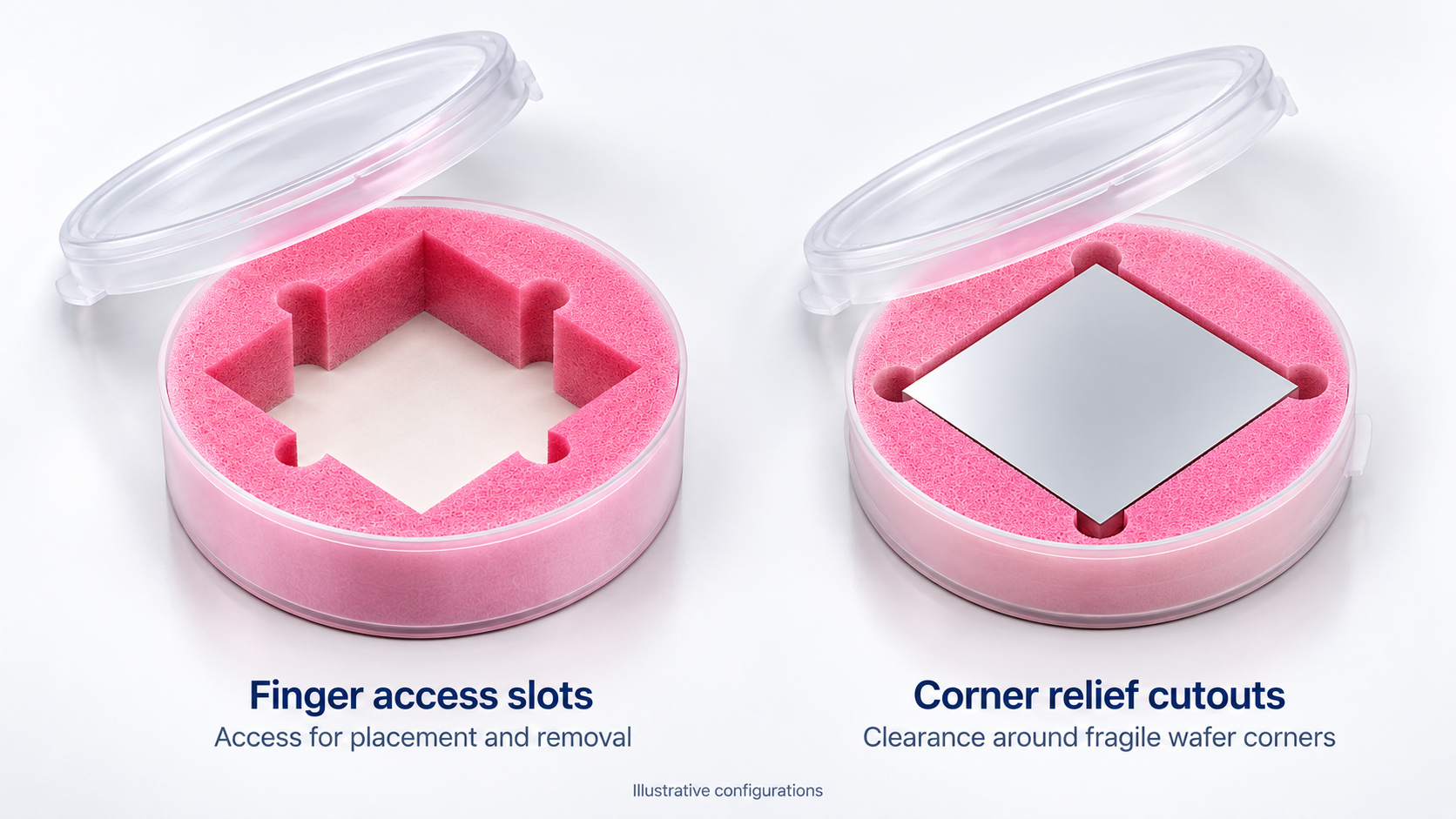
Along the sides
Finger access slots
Rounded cutouts centered along the sides of the foam opening provide finger access for wafer placement and extraction. Their location creates access where a continuous foam wall would otherwise limit the operator’s reach.
Slot size and position should suit the established handling method and the areas of the wafer that may be touched.
At the corners
Corner relief cutouts
Cutouts at the vertices of the square opening provide clearance around the wafer’s sharp corners. This is particularly useful for very thin wafers, where a corner that catches on the foam can chip or break.
The relief gives the corner room to pass without catching as the wafer is placed or removed.
When I review a custom square-wafer configuration, I distinguish access for handling from clearance around vulnerable corners. The examples above illustrate those separate functions. The wafer outline, thickness, and handling requirements determine which features belong in the foam design. [4]
Wafers mounted in dicing frames or wafer rings
A wafer supported on dicing tape and a frame is a different packaging object from a loose wafer. In wafer dicing, the wafer is divided into individual dies; the tape and frame support the mounted material during the process. Suppliers also use terms such as wafer ring and film frame. [5]
I have also adapted Malaster jars for wafer rings or frames with the wafers mounted in them. The design starts with the complete mounted assembly: frame outline, thickness, tape position, wafer position, and any projecting features.
A wafer diameter alone is insufficient for this review. The frame can extend beyond it, and the usable support locations depend on the frame design. Identify the frame areas that may carry the load and the wafer or exposed tape areas that must remain clear. Foam can then be configured around those permitted support locations.
Dicing blades supported through the center hole
I have configured Malaster’s 8-inch wafer jars for wafer-processing saw blades and other processing tools. For dicing blades, the important packaging question is where the holder can support the blade while keeping its cutting edge untouched.

For one blade-holder configuration, I used an antistatic closed-cell foam stack with an overall diameter of 170 mm and a height of 2.5 inches. The holder supports the blades through their center holes, keeping the outer cutting edges clear of the foam.
63.5 mm = 2.5 inches
These dimensions describe the complete foam stack. They are not the blade diameter or the center-support diameter.
The center opening becomes the locating feature. The surrounding space must preserve cutting-edge clearance as the blade is loaded, held, and removed.
Dicing blades are supplied in different forms, including hubbed and hubless designs. [5] For a new holder, provide the actual blade outer diameter, center-hole diameter, thickness, hub or projection details, and quantity. Those dimensions determine whether an existing support arrangement can be adapted or a different foam geometry is needed.
The useful design question: where can this part be supported?
A conventional wafer stack, a mounted wafer frame, and a dicing blade have different contact requirements. Customization brings the jar, foam geometry, and handling method together around the particular part.
A practical configuration reference
Wafer jar configuration concerns and what to check
Use these checks when reviewing a new part or changing an existing packaging arrangement. They connect an observed concern with the dimensions, contact areas, or assembly details that need attention.
Swipe the table horizontally to see the concern, checks, and configuration decision.
| Situation | What to check | Configuration decision |
|---|---|---|
| A square wafer appears to fit by width | Actual diagonal, corner profile, usable jar space, and foam allowance. | Confirm the complete outline fits with the intended support and clearance. |
| The wafer is difficult to place or remove | Handling method, permitted contact areas, and access along the sides. | Review finger access slot locations and size while retaining the required foam support. |
| Sharp wafer corners can catch | Wafer thickness, corner shape, and clearance through the loading and removal path. | Review corner relief cutouts to give the vulnerable tips clearance from the foam. |
| A partial load moves inside the jar | Stack height at the reduced wafer count, separator count, and cushion thicknesses. | Review the cushioning arrangement for the intended load range. |
| The lid requires excessive force | Combined wafer, separator, and cushion thicknesses against usable internal depth. | Reassess stack height and intended compression before closing the jar. |
| A dicing blade fits within the jar | Center-hole fit, blade profile, hub details, cutting-edge clearance, and removal access. | Establish permitted support areas and preserve cutting-edge clearance throughout handling. |
| A mounted wafer needs packaging | The complete frame-and-wafer assembly, including tape position and projecting features. | Size the interior around the assembly and its permitted frame support locations. |
Record the selected jar, foam components, separators, quantities, and layer sequence together. This gives repeat orders and any later changes a clear configuration to reference.
Make the next conversation useful
What should you send Malaster for a custom configuration?
A drawing or sample, the intended quantity per jar, and the contact requirements provide a useful starting point. An existing jar part number or packaging sample can also help establish what should be retained or changed.
- Part geometryFull outline, thickness, tolerances, and projections. Include blade center-hole dimensions or the complete mounted-frame outline where relevant.
- Permitted contactAcceptable support areas and surfaces, edges, coatings, or features that must remain clear.
- Quantity per jarNormal load and any minimum or maximum quantity the configuration must accommodate.
- Existing packagingJar part number, current foam or separator information, drawings, and photographs.
- Handling methodHow the part is loaded, removed, transferred, stored, or shipped, including any finger access or corner-clearance needs.
- Application requirementsSpecified materials, electrostatic-control requirements, cleanliness, and contact compatibility.
- Program needsInitial quantity, expected repeat usage, and required date.
- Reason for the changeA new shape, unwanted movement, difficult removal, or another defined packaging concern.
You do not need a finished packaging design before contacting Malaster. Send the information you have so the jar, custom foam, and separator options can be reviewed together.
Practical answers
Frequently asked questions about wafer jar packaging
Where do Tyvek separators go in a conventional wafer jar?
In the illustrated Tyvek-separated assembly, place Tyvek between every pair of silicon wafers and between each foam cushion and the wafer face next to it. Three wafers between upper and lower cushions use four Tyvek separators. Intermediate foam or other customer-specified arrangements can change the layer count.
Can a round wafer jar hold square solar wafers?
Yes, when the complete outline fits with the selected foam and clearances. Malaster has configured 6-inch wafer jars for various sizes of square solar wafers. Check the actual diagonal and corner geometry against usable interior space.
Why do square-wafer foam inserts have cutouts in different places?
Side-centered cutouts act as finger access slots for wafer placement and removal. Corner relief cutouts provide clearance around sharp wafer corners to reduce the risk of catching on the foam, particularly with very thin wafers. Their locations follow different handling and protection needs.
Can Malaster configure jars for wafers on dicing frames?
Yes. Malaster has adapted jars for wafer rings or frames with wafers mounted in them. Provide the complete frame-and-wafer assembly dimensions, permitted support areas, and loading method so the interior can be evaluated.
How can a foam holder keep a dicing blade’s cutting edge clear?
One Malaster configuration supports blades through their center holes using a custom antistatic closed-cell foam stack. The cutting edges remain clear of the foam. A new design requires the blade’s outer diameter, center hole, thickness, hub details, and intended quantity.
Can I request BLAC wafer separators if they are not listed online?
Yes. Contact Malaster with the required outline, dimensions, quantity, and application requirements. BLAC is available for standard and custom interleave configurations, including MC-6BLAC; Malaster can review the appropriate finished configuration and current availability.
How many wafers can a jar hold?
Capacity depends on wafer thickness and quantity, separator thickness and count, the foam arrangement, and usable internal depth. Evaluate closure at the intended foam compression. Customers using more intermediate cushioning may package fewer wafers in the same jar.
Bring us the part. Start with the fit.
Let’s configure the interior around your application.
Send a drawing, dimensions, or photographs, along with the quantity per jar and any contact restrictions. Malaster can evaluate an existing wafer jar with standard or custom foam components and suitable separators.
Looking for a complete assembly? Explore WafPak wafer packaging systems and confirm the configuration for your wafer and handling requirements.
Technical basis and application experience
This guide combines Malaster material information with application experience from Mike Cordingley, who has worked in semiconductor and electronics packaging since 1995. The square-wafer, mounted-frame, and blade-holder examples describe Malaster application work. The images are illustrations; the blade-holder rendering and square-wafer cutout comparison are based on Malaster design references. Illustrations explain component relationships and do not replace a dimensioned configuration drawing.
- AFD and AFDF: Malaster’s current material records and supplier technical information, including MDS-AFDF-001, Antistatic Closed-Cell Polyethylene Foam, Rev A. Detailed material information is available for application review.
- Tyvek separators: Malaster’s Tyvek wafer separator range. Material grade and part-specific requirements should be identified when specifying a configuration. Tyvek® is a trademark of DuPont.
- BLAC: MDS-BLAC-001, Conductive Black Polyethylene, Rev A, effective September 7, 2026. The material description and nominal thickness in this article follow that datasheet. Contact Malaster for the current customer copy and application-specific electrical documentation.
- Custom square-wafer features: Malaster design models MC-806JLL and MC-604SW, with the finger-access and corner-relief functions described by Mike Cordingley. The comparison image illustrates these functions rather than relative jar sizes.
- Dicing terminology: UKAM Industrial Superhard Tools, From Silicon Wafer to Microchip: The Role of Dicing in Integrated Circuit Manufacturing. Used for process, frame, and blade terminology. Malaster application examples are based on Mike’s own work.