
ESD Packaging Resources, Packaging Design, Packaging Materials, Recently Updated
How to Specify a Custom ESD Foam Insert for Electronic Components
Aug
Custom Foam Insert Specification
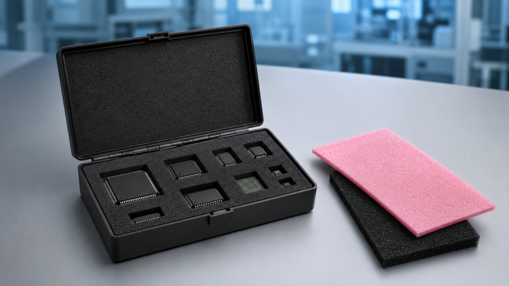
A custom ESD foam insert should be designed around the component, the surrounding package and the work the foam must perform.
Start with a drawing, CAD file, sample or accurate dimensions. Identify delicate features and surfaces that need clearance, provide the available box space and quantity, and include any defined electrical or cleanliness requirements. Malaster can review what you have and identify what still needs to be confirmed before the insert design and manufacturing method are finalized.
Start With the Application
What Information Does Malaster Need?
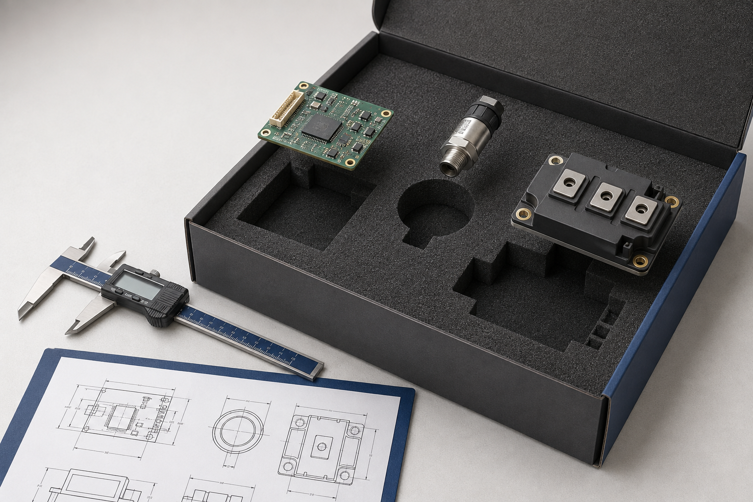
The component is the best place to start. A technical drawing, CAD file, physical sample, photographs or accurate dimensions establish the geometry and reveal features that may affect how the insert should support the part.
Malaster also needs to understand what the foam must accomplish. One application may primarily need cushioning. Another may need defined component positions, conductive contact, clearance around sensitive features, separation between parts or several functions at the same time.
Component
Drawing, sample or dimensions, including leads, connectors, projections and sensitive surfaces.
Package
Existing box part number or usable internal length, width and height, including any lid cushion.
Program
Initial quantity, expected repeat usage, handling conditions, cleanliness requirements and required date.

Geometry and Handling
Why Contact Areas and Clearance Change the Cavity
Overall length, width and height do not always show how a component should be supported. A drawing can reveal leads, pins, connectors, projections, recessed areas, optical surfaces, coatings and other features that change the cavity.
Two components with similar outside dimensions may therefore need different inserts. One may tolerate support along the full body. Another may require perimeter support while leads or a raised surface remain completely clear of the foam.
Identify Where Foam May Contact
Mark the body, perimeter or other approved areas that can carry the component’s weight or provide retention. If conductive contact with leads or terminals is intentional, identify that requirement separately.
Identify Where Foam Must Not Contact
Mark leads, connectors, optical surfaces, coatings, delicate components and other protected features. These areas may require added clearance even when they fall inside the component’s maximum dimensions.

Material Selection
Separate the Electrical Requirement From the Physical Construction
Electrical behavior and physical foam construction are related decisions, but they are not the same decision. First establish what electrical role the foam must perform. Then evaluate which construction provides the required cushioning, firmness, cleanliness, recovery and component support.
Electrical Requirement
If a customer drawing, internal specification or ESD-control requirement identifies conductive, antistatic or another documented material behavior, include it with the inquiry. Do not select foam from color alone.
Review the Pink Antistatic Foam vs. Black Conductive Foam guide for Malaster material families and supplier-reported electrical data.
Physical Construction
Soft cushioning, firm positional support, repeated compression, moisture behavior, cleanliness and component contact can lead to different foam constructions.
Consider available thickness, desired retention, ease of removal, reuse, particulate requirements and whether the foam will be repeatedly compressed.
Package Integration
Does the Insert Need to Fit an Existing Box?
If the insert will be installed in an existing box, container or packaging assembly, provide the box part number or usable internal dimensions. The available space inside the package matters more than the nominal outside dimensions.
| Information to Provide | Why It Matters |
|---|---|
| Box part number | May allow Malaster to identify the existing packaging configuration. |
| Usable internal length and width | Establishes the maximum practical insert footprint. |
| Available internal height | Helps determine foam thickness and vertical component clearance. |
| Existing insert or cushion | Provides a reference for fit, thickness, cavity layout and construction. |
| Lid or top-cushion requirement | Affects vertical retention, compression and protected-feature clearance. |
If the requirement is only for flat replacement cushioning rather than component-specific cavities, review the available ESD box foam cushions before specifying a custom insert.
Production Method
When Should Laser-Cut or Die-Cut Foam Be Considered?
The conversion method should follow the material, cavity geometry, quantity, design stability and cleanliness requirements. Customers do not need to choose the process before Malaster reviews the application.
Laser-Cut Foam
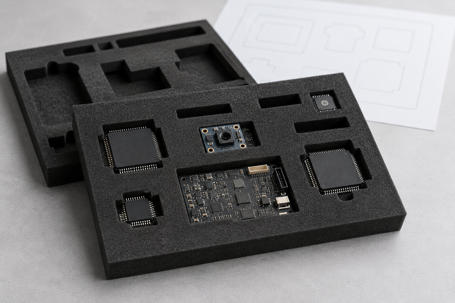
Laser cutting can be practical for prototypes and lower-volume production because it avoids conventional cutting-die tooling and allows design changes without replacing a die.
The specific foam, edge condition, cleanliness and foreign object debris requirements must still be reviewed. Laser processing may leave slight cosmetic carbon residue along cut edges.
Die-Cut Foam
Die cutting can be appropriate for established repeat-production programs when the design is stable and expected quantity supports the tooling investment.
It can provide an efficient, repeatable production method after the insert configuration has been approved.
There is no universal quantity at which every insert should change from laser cutting to die cutting. Material, cavity geometry, tooling complexity, expected repeat usage and application requirements all affect that decision.
Project Checklist
Custom ESD Foam Insert Specification Checklist
Not every item applies to every insert, but resolving these questions early can reduce unnecessary revisions.
Component
Identity and Geometry
Part number when applicable, drawing, CAD file, sample, photographs or dimensions.
Contact
Support and Clearance
Approved foam contact areas plus leads, connectors and surfaces that must remain clear.
Material
Electrical and Mechanical Role
Required electrical behavior, cushioning, positioning, retention, separation and cleanliness.
Package
Usable Space
Box part number, internal dimensions, available height and any lid or bottom cushions.
Production
Quantity and Repeat Usage
Prototype quantity, initial production quantity, estimated repeat usage and design stability.
Operation
Handling and Schedule
Storage, shipping, repeated access, reuse, FOD controls, approval milestones and required date.
Avoidable Delays
Common Specification Gaps
Providing only length, width and height
Overall dimensions may not show leads, connectors, projections or sensitive surfaces. Provide the actual component drawing when these details affect support or clearance.
Assuming every surface can touch the foam
Identify areas that should remain free from contact. The cavity should support the component in appropriate locations rather than simply match its outline.
Selecting foam by color
Color can identify a material family, but electrical behavior must be confirmed from the documented properties of the actual material and the application requirement.
Using outside box dimensions
The insert must fit the usable space inside the package. Wall construction, lid cushions, dividers and other features may reduce the available dimensions.
Choosing the cutting method before defining the project
Quantity, material, design stability, geometry and cleanliness requirements should be understood before laser cutting, die cutting or another process is selected.
Frequently Asked Questions
Custom ESD Foam Insert Questions
Do I need a finished CAD file?
No. A CAD file can help, but Malaster can begin evaluating an application from a technical drawing, dimensions, photographs, physical sample or existing insert. Additional information can be identified during review.
Can Malaster design the insert around my component?
Yes. Malaster can evaluate cavity geometry, overall insert dimensions, foam thickness, component clearances and package constraints using the component and application information provided.
Can I send an existing insert as a sample?
Yes. An existing insert can provide useful information about overall size, thickness, cavity layout and the way the current package supports the component. Include anything that needs to change in the replacement.
Is conductive foam always required?
No. Antistatic and conductive foam perform different electrical roles, and foam is only one part of the ESD packaging system. Selection should be based on the device, package design, documented material properties and applicable requirements.
Can Malaster provide the box as well as the insert?
Yes. If you already have a box, provide its part number or usable internal dimensions. If the surrounding package is also needed, include that requirement with the custom foam request.
Continue Exploring
Related Malaster Resources
Antistatic vs. Conductive Foam
Compare Malaster foam families, constructions, electrical behavior and supplier-reported material data.
Available ESD Foam
Browse standard conductive and antistatic foam products for electronics packaging.
ESD Fundamentals
Review ESD-control principles, material classifications, handling and protective packaging.
Custom Foam Application Assistance
Send Malaster Your Drawing, Sample or Packaging Requirements
Start with the information you already have. Send a drawing, CAD file, dimensions, photographs, physical sample or existing package, along with the quantity and required date. Malaster can identify the remaining information needed to evaluate a practical custom foam insert.
Prefer to discuss the application? Call 408-745-0104.
