
ESD Packaging Resources, Custom Packaging Solutions, Featured, Recently Updated
ESD Boxes for Electronic Components: Materials, Foam Inserts & Device Protection
Aug
ESD boxes for electronic components help protect sensitive semiconductor devices during manufacturing, handling, storage, and transportation. However, selecting an ESD-safe box alone does not create a complete protective package.
An effective ESD packaging system must address both electrostatic protection and mechanical protection. Depending on the component and handling process, that system may combine a conductive protective box with conductive or static-control foam, a precision die-cut or laser-cut insert, a rigid thermoformed device insert, lid retention, or an additional static-shielding barrier.
The objective is not simply to place a sensitive component inside an ESD box. The package should control electrostatic risk while also limiting movement, abrasion, impact, bent leads, damaged terminals, and contact between adjacent devices.
Quick Answer
The best ESD box for an electronic component is one that works with the correct internal packaging. A standard conductive enclosure combined with properly selected foam or a precision device insert can create a component-specific system that provides both ESD control and mechanical protection.

How Do ESD Boxes for Electronic Components Work?
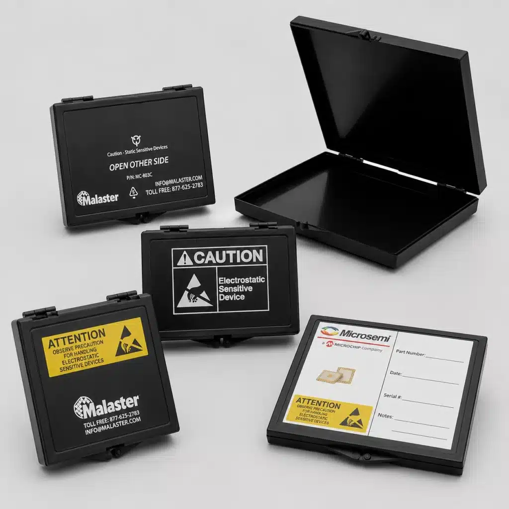
An ESD box is a protective enclosure made from material selected to help control electrostatic charge around sensitive electronic products. Depending on the application, these products may also be described as conductive boxes, ESD protective boxes, ESD storage boxes, or ESD shipping boxes.
They are commonly used for integrated circuits, semiconductor devices, electronic assemblies, sensors, optoelectronic components, precision electronics, and other electrostatic discharge sensitive items.
Malaster’s black conductive protective boxes are manufactured from a conductive material identified as RTP 199 X 26017 C BLACK. Within Malaster part numbering, the designator C identifies the conductive box material, as seen in products such as the MC-803C.
Representative material data includes a surface resistivity of less than 105 ohms/square, surface resistance of less than 104 ohms, and static decay of less than 0.10 second. These values apply to the specified box material and should not be treated as universal specifications for every product marketed as an ESD box.
The enclosure itself, however, is only the starting point. Internal packaging determines how the component is positioned, separated, cushioned, and retained. A conductive box with an improperly designed insert can still allow a component to move, abrade, collide with another device, or suffer lead and terminal damage.
For this reason, Malaster approaches an ESD protective box as one element of a complete protective packaging system rather than as an isolated container.
Conductive, Static-Dissipative and Low-Charging Materials
ESD-control packaging materials are not interchangeable. Conductive, static-dissipative, and low-charging or antistatic materials can perform different functions within the same packaging system.
The correct choice depends on the component, direct-contact conditions, required mechanical support, handling environment, packaging configuration, and the customer’s ESD control requirements.
| Material Type | Primary Function | Typical Malaster Use | Key Consideration |
|---|---|---|---|
| Conductive | Allows charge to move through the material relatively readily. | Protective boxes and black ESD foam configurations. | Actual electrical properties must be confirmed from the specified material. |
| Static-Dissipative | Provides controlled dissipation of electrostatic charge. | Thermoformed HIPS device inserts and selected cushioning materials. | Should not automatically be substituted for a conductive material. |
| Antistatic / Low-Charging | Helps reduce charge generation during contact and separation. | Pink polyurethane and polyethylene cushioning materials. | Low-charging behavior does not automatically provide conductivity or discharge shielding. |
| Static-Dissipative HIPS | Combines rigid formed geometry with static-dissipative electrical properties. | Thermoformed semiconductor device inserts and base/lid retention systems. | Component fit and cavity geometry are as important as electrical performance. |
Black is commonly associated with conductive packaging because carbon-based additives are frequently used to create conductive properties. However, color alone is not an electrical specification.
The same principle applies to pink foam. Pink coloration is commonly associated with antistatic or low-charging materials, but the exact electrical properties depend on the particular foam grade.

Foam Options for ESD Protective Boxes
Foam is one of the most versatile components in an ESD protective box because it can provide cushioning, component retention, separation, and electrostatic control within the same packaging system.
Malaster commonly works with four basic foam configurations for these box systems: a softer black conductive foam, a firmer black conductive foam, a softer pink static-control foam, and a firmer pink static-control foam.
These materials are not selected by color alone. Their electrical behavior, cellular structure, firmness, compression characteristics, thickness, cleanliness, and intended function all influence which foam is appropriate.
Soft Black Conductive Foam
A softer black foam can be used when the package requires conformable cushioning or lid compression around a sensitive component.
One Malaster material used for this purpose is designated CFS. It is a flexible urethane foam with a density of approximately 1.7 to 1.9 lb/ft³. Representative electrical data lists surface and point-to-point resistance in the 103 to 105 ohm range and a static decay time of 0.01 second maximum.
Its softer construction makes it particularly useful where the foam must compress around a component rather than define a rigid cavity.
Firm Black Conductive Foam
For firmer component support and precision-cut cavities, Malaster can use conductive cross-linked polyethylene foam. A common material family is identified by Malaster designators such as CFF or LD32.
LD32 conductive polyethylene foam has a nominal density of approximately 2.0 lb/ft³ and representative volume resistivity of 5 × 10³ ohm-cm. Its closed-cell, cross-linked construction provides greater firmness and dimensional stability than softer urethane cushioning.
This type of foam is well suited to precision-cut inserts where the cavity itself must help establish component position.
Soft Pink Static-Control Foam
Malaster also uses pink polyurethane foam where resilient, lower-force cushioning and low-charging behavior are appropriate.
Material identified by designators such as AFD or ASL is an open-cell antistatic polyurethane foam with representative surface resistivity of approximately 108 to 1012 ohms/square and static decay of less than 5 seconds.
Firm Pink Static-Control Foam
A firmer pink polyethylene construction can be used where a closed-cell material and greater shape retention are desirable.
Malaster designators such as AFDF and ASF identify a Cell-Aire® polyethylene foam family available in antistatic grades. Representative electrical data includes surface resistivity of approximately 109 to 1012 ohms and static decay of less than 2 seconds.
Why Both Electrical Properties and Firmness Matter
Two foams can both be appropriate for ESD packaging while behaving very differently mechanically. A soft foam may be ideal for lid cushioning and controlled compression, while a firmer material may be better for precision cavities and component positioning. Material selection therefore considers both ESD performance and the mechanical job the foam must perform.
Malaster supplies standard ESD box foam cushions and can develop custom foam configurations when a standard pad does not adequately locate, separate, or protect the component.
Foam Must Provide Mechanical Protection Too
Electrical performance is only one part of foam selection. The foam must also support the product correctly.
Important mechanical considerations include:
- Foam firmness and compression characteristics
- Component weight and geometry
- Lead, pin, terminal, and connector configuration
- Foam thickness and cavity depth
- Lid compression
- Shock and vibration exposure
- Storage duration
- Particulate and cleanliness requirements
Too little retention can allow a device to shift inside the package. Too much compression can place unnecessary force on delicate semiconductor packages, leads, terminals, or electronic assemblies.
Foam should therefore be treated as an engineered component of the package rather than simply as filler material.
Die-Cut and Laser-Cut ESD Foam Inserts
When a flat foam cushion cannot adequately position or separate the component, a custom foam insert can be designed around the device geometry.
Malaster can produce custom foam inserts using die cutting or laser cutting. Both processes can create component-specific cavities, but they solve different production problems.
Die-Cut Foam Inserts
Die cutting is generally the preferred approach when the same insert will be produced repeatedly in higher quantities and tighter repeatability is important.
A dedicated cutting die establishes the cavity geometry and allows the same pattern to be reproduced efficiently across a production run.
Die-cut inserts can be designed to:
- Separate individual electronic components
- Maintain a defined device orientation
- Protect exposed leads, pins, or terminals
- Reduce movement during handling and shipment
- Create finger-access areas for easier unloading
- Organize a specified quantity of components per package
- Repeat the same cavity matrix consistently across larger production quantities
Laser-Cut Foam Inserts
Laser cutting eliminates the cost of a dedicated cutting die and is therefore particularly useful for prototypes, lower quantities, development programs, and designs that may change before they reach repeat production.
It also provides considerable flexibility for unusual or complex profiles. The laser cuts through the foam according to the programmed geometry, allowing new cavity layouts to be created without first manufacturing physical die tooling.
Laser cutting should not, however, be assumed to provide exactly the same dimensional behavior as a production die-cut insert. Practical tolerances can be influenced by factors including laser kerf, foam thickness, material construction, compression, and the geometry being cut.
For that reason, Malaster considers production quantity, tolerance requirements, material, cavity geometry, and tooling economics when deciding which process is appropriate.

Packaging Design Principle
Custom packaging does not have to mean that every element is custom. A standard conductive box combined with a custom die-cut or laser-cut foam insert can provide application-specific component retention without requiring a completely new outer enclosure.
Static-Dissipative HIPS Thermoformed Device Inserts
Foam is not the only way to retain sensitive electronic components inside an ESD protective box.
For semiconductor packages that benefit from a rigid, precisely formed cavity, Malaster also manufactures thermoformed device inserts for semiconductor packaging.
A material commonly used for these inserts is Malaster MC-030CS, a rigid high-impact polystyrene film designed for thermoforming applications requiring static-dissipative properties.
The material is black with a slight gloss/matte surface character and has a manufacturer-listed typical conductivity range of approximately 104 to 107 ohms per square.
This distinction is important: the thermoformed insert should be described as static-dissipative HIPS, rather than simply being grouped with the more conductive black box material.
Thermoforming allows the material to be shaped into defined pockets, shoulders, relief areas, and retention features. Instead of relying on a compressible foam cavity, the component can be located by rigid formed geometry designed around the package.
When a Thermoformed Device Insert Makes Sense
Static-dissipative HIPS inserts can be particularly useful when the application requires:
- Repeatable component positioning
- Individual device separation
- Controlled orientation
- Protection of fine-pitch leads or package edges
- Efficient loading and unloading
- Defined quantities per package
- Reusable packaging
- A rigid alternative to a foam cavity
Malaster supports device inserts for many semiconductor package families, including QFP, TQFP, PQFP, BGA, CGA, PLCC, LCC, DIP, SOIC, SOJ, SOP, TSOP, TSSOP, and other configurations.
When an existing insert does not match the device, a custom thermoformed configuration can be developed around the component dimensions, lead geometry, handling method, and desired quantity per box.
Combining Thermoformed Inserts with Foam
A static-dissipative HIPS insert can be combined with conductive or other appropriate ESD-control cushioning when the package also requires vertical restraint or additional shock protection.
For example, the rigid insert can establish horizontal position and separation while lid foam provides controlled compression when the box is closed.
Foam-Free Base and Lid Retention
Some applications can be designed without foam.
A thermoformed base insert can be paired with a corresponding formed lid insert so that the component is retained between two rigid surfaces designed around its geometry. This approach can be useful when repeatable positioning, reduced foam particulate, reusable packaging, or a cleaner loading environment are important considerations.

How to Choose the Right ESD Box Packaging System
The most effective packaging selection process starts with the component and works outward.
Starting with an arbitrary box size and then asking the internal packaging to compensate for excessive empty space can result in unnecessary material, poor retention, or an inefficient package.
1. Identify the Component
Document the overall dimensions, weight, package type, lead or terminal configuration, sensitive surfaces, and required quantity per box.
A drawing, CAD file, specification sheet, physical sample, or clear dimensional photograph can be extremely useful during the packaging evaluation.
2. Define the Application
Determine how the package will actually be used. Requirements can differ substantially between work-in-process handling, inventory storage, returnable transport, customer shipment, field service, and long-term storage.
3. Establish the ESD Requirements
Identify the electrical properties required by the customer’s ESD control program and determine whether conductive, static-dissipative, low-charging, or discharge-shielding performance is required.
4. Evaluate Mechanical Risks
Consider movement, shock, vibration, abrasion, stacking, lid pressure, repeated handling, and the possibility of contact between adjacent devices.
5. Select the Internal Retention Method
Choose the internal packaging according to how precisely the product must be positioned, the required production quantity, and how personnel will load and remove it.
| Application Need | Typical Packaging Approach |
|---|---|
| General cushioning and movement control | Conductive box with base and lid foam cushions |
| Repeat cavities at higher production quantities | Die-cut ESD foam insert |
| Prototype or lower-quantity custom cavities | Laser-cut ESD foam insert |
| Precise rigid semiconductor positioning | Static-dissipative HIPS thermoformed device insert |
| Foam-free rigid retention | Thermoformed base and lid insert system |
| Additional discharge shielding required | Evaluate an appropriate shielding barrier as part of the complete package |
| Identification, branding, or traceability | Custom full-color printed conductive box |
6. Consider Loading and Unloading
A package should protect the component without making it unnecessarily difficult to use.
Finger clearance, cavity spacing, component orientation, lid opening, labeling, and unloading sequence can all affect practical performance.
7. Evaluate the Complete Package
The box, foam, thermoformed insert, closure, shielding layer, labeling, printing, and shipment method should be evaluated together.
The strongest packaging designs result from these elements working as a system rather than being selected independently.
Custom Full-Color Printing for ESD Protective Boxes
The outside of an ESD box can provide more than structural protection. It can become part of the customer’s identification, traceability, handling, inventory, and branding system.
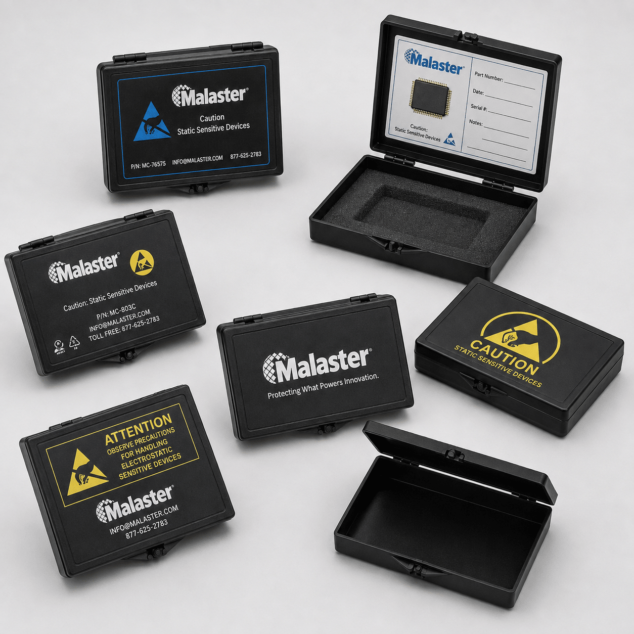
Malaster can provide custom full-color printing directly on conductive protective boxes, allowing customers to move beyond a plain black enclosure, applied sticker, or simple monochrome marking.
Custom printing can incorporate:
- Company logos and brand graphics
- Product names and part numbers
- ESD handling symbols and warnings
- Assembly or handling instructions
- Barcodes and identification graphics
- Serialized or program-specific information
- Color-coded product identification
- Write-in information areas
- Full-color graphics and product imagery
This capability can be especially valuable for reusable packaging. Instead of relying entirely on removable labels, the box itself can become a clearly identifiable component of the customer’s manufacturing, inventory, service, or distribution process.
For semiconductor manufacturers, electronics companies, aerospace and defense programs, medical device manufacturers, contract manufacturers, and other organizations using controlled component packaging, professional exterior printing can improve identification while creating a much more finished presentation for the end customer.
Custom printing does not replace the electrical or mechanical requirements of the package. It adds identification, communication, traceability, and branding to an already properly engineered ESD packaging system.
Learn more or submit artwork through Malaster’s custom product printing request.
Conductive Packaging and Discharge Shielding
One important distinction in ESD packaging is the difference between conductivity and discharge shielding.
A conductive box should not automatically be assumed to provide complete discharge shielding simply because its material is electrically conductive. Shielding performance depends on the construction and performance of the complete packaging system.
Important Distinction
Conductive, static-dissipative, low-charging, and discharge-shielding properties describe different aspects of ESD packaging performance. The required properties should be determined by the application and the customer’s ESD control program.
Some applications therefore combine a conductive protective box with an ESD or static-shielding bag when an additional protective barrier is required.
Packaging materials should be selected and verified according to the applicable ESD-control requirements for the component and handling environment. For current packaging-material requirements and test methods, refer to ANSI/ESD S541-2026 from the EOS/ESD Association.
Common ESD Box Packaging Mistakes
Treating All ESD Materials as Interchangeable
Conductive, static-dissipative, and low-charging materials do not perform the same function. A material should not be substituted simply because it is generally described as ESD-safe.
Selecting the Box Before Evaluating the Component
An unnecessarily large enclosure creates space that the internal packaging must then control. Starting with the component dimensions, retention requirements, and handling process usually results in a more efficient design.
Allowing Excessive Component Movement
A component can be electrically protected and still suffer mechanical damage.
Repeated movement can result in abrasion, impact damage, bent leads, chipped package edges, damaged terminals, or contact between adjacent devices.
Applying Too Much Lid Compression
Foam or retention features that are too thick can place unnecessary pressure on sensitive components. Lid retention should control movement without applying damaging force to leads, connectors, terminals, or package surfaces.
Assuming Foam Color Defines Its Electrical Performance
Black and pink are useful visual conventions, but appearance is not a material specification. Electrical performance should be confirmed from the actual material being used.
Choosing a Cutting Process Based Only on Tooling Cost
Laser cutting can eliminate dedicated die tooling, but the lowest initial tooling cost does not always make it the best production process. Quantity, tolerance requirements, foam thickness, cavity geometry, and repeatability should also be evaluated.
Ignoring the Customer’s Unpacking Process
A package can protect a component successfully during transportation yet create unnecessary handling risk when an operator attempts to remove it.
Device orientation, finger access, cavity spacing, labeling, and unloading sequence should therefore be considered during the packaging design.
Inspection, Storage and Reuse
Many conductive boxes, foam systems, and thermoformed inserts can be reused when they remain clean, structurally sound, correctly identified, and appropriate for the application.
Reusable packaging should be periodically checked for:
- Cracks, tears, or physical damage to the box
- Damaged hinges, corners, or closure features
- Compressed or deteriorated foam
- Torn, distorted, or damaged cavities
- Damaged thermoformed retention features
- Contamination
- Incorrect or outdated product identification
- Changes in fit that allow excessive component movement
Cleaning procedures should be compatible with the packaging material and the customer’s ESD control process. Solvents, household cleaners, or uncontrolled wiping materials should not be introduced without confirming that they are appropriate for the specific material.
Building a Complete ESD Packaging System
One of the advantages of an integrated packaging approach is the ability to choose the technology that best solves each part of the problem.
A complete Malaster ESD box system may combine:
- A conductive protective box
- Soft conductive foam
- Firm conductive foam
- Pink static-control cushioning foam
- Die-cut custom foam cavities
- Laser-cut custom foam profiles
- A static-dissipative HIPS thermoformed base insert
- A formed thermoformed lid-retention insert
- A static-shielding bag when required
- Custom full-color exterior printing
- Part identification and handling information
The important point is that custom packaging does not require every component of the package to be custom.
A standard conductive box can often serve as the platform while the foam, thermoformed insert, lid retention, printing, or labeling is customized around the component and its handling process.
What Information Helps When Designing an ESD Box System?
A packaging project can often begin with basic component information. The following details help Malaster determine whether an existing configuration will work or whether a custom insert or packaging system should be considered:
- Component drawing or dimensional sketch
- Overall length, width, and height
- Semiconductor package type, when applicable
- Lead, pin, terminal, or connector configuration
- Component weight
- Quantity required per box
- Known ESD material requirements
- Required dimensional tolerances
- Storage and transportation conditions
- Expected production quantity
- Preferred foam or insert configuration, if known
- Required labeling or custom printing
- Drawings, photographs, CAD data, or physical samples when available
Not every detail has to be known before the conversation begins. In many cases, reviewing the component and intended handling process is enough to determine what additional information is needed.
Need Help Configuring an ESD Protective Box System?
Malaster can help determine whether your component is best protected with a standard conductive box, conductive or static-control foam, a custom die-cut or laser-cut insert, a static-dissipative thermoformed device carrier, or a combination of these technologies.
Send the component dimensions, package information, desired quantity per box, handling requirements, tolerance requirements, drawings, photographs, or samples you have available. We can use that information to evaluate a practical packaging approach.
Frequently Asked Questions About ESD Boxes
What is an ESD box?
An ESD box is a protective enclosure made from material selected to help control electrostatic charge around sensitive electronic components. Depending on the application, the complete system may also include conductive or static-control foam, thermoformed inserts, shielding materials, and other retention components.
Are all black ESD boxes electrically the same?
No. Color alone does not define electrical performance. Malaster’s conductive protective boxes use a specified conductive material with documented electrical characteristics, but products made from other materials may have different properties.
What is the difference between soft and firm ESD foam?
Soft foam is generally better suited to conformable cushioning and controlled compression, while firmer foam provides greater dimensional support for precision cavities and component positioning. Electrical properties and mechanical firmness should both be considered when choosing the material.
Can pink antistatic foam replace conductive black foam?
Not automatically. Pink low-charging materials and conductive black foams can have substantially different electrical properties. The correct material depends on the ESD-control requirement and the mechanical function the foam must perform.
What is the difference between a die-cut and laser-cut foam insert?
Die cutting uses dedicated tooling and is generally advantageous for higher-volume repeat production where consistent cavity geometry and tighter process control are important. Laser cutting requires no physical die and can be attractive for prototypes and lower quantities, although practical dimensional tolerances can be influenced by kerf, foam thickness, material construction, and cavity geometry.
What material does Malaster use for thermoformed ESD device inserts?
A common Malaster material is MC-030CS, a black rigid high-impact polystyrene film designed for thermoforming applications requiring static-dissipative properties. Its manufacturer-listed typical conductivity range is approximately 104 to 107 ohms per square.
When should a thermoformed insert be used instead of foam?
A thermoformed insert is particularly useful when a component requires rigid individual cavities, controlled orientation, repeatable positioning, or a reusable retention system. Foam and thermoformed inserts can also be combined within the same box.
Does a conductive box automatically provide discharge shielding?
No. Conductivity and discharge shielding are different packaging properties. Shielding performance depends on the complete package construction and should be evaluated according to the requirements of the application.
Can ESD protective boxes be custom printed?
Yes. Malaster can add custom full-color printing for company branding, part identification, barcodes, handling instructions, ESD graphics, color coding, write-in fields, and other application-specific information.
Can a standard ESD box be combined with a custom insert?
Yes. This is often one of the most practical approaches to custom ESD packaging. A standard conductive box can be paired with a custom die-cut or laser-cut foam insert or a thermoformed static-dissipative device insert designed around the component.
Related ESD Packaging Resources
- ESD Protective Boxes
- ESD Box Foam Cushions
- Semiconductor Device Inserts
- Custom Foam Inserts
- Custom Product Printing
- ESD Bags
- Custom ESD Packaging Consultation
- Malaster Product Hub
