
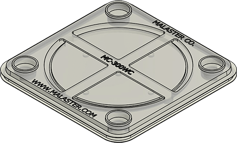
MC-300WC 300 mm Wafer Carrier, 25 mm Deep
MC-300WC 300 mm wafer carrier with a listed depth of 25 mm. ESD PETG enclosure. Internal foam and separators are selected separately. Explore WafPak assemblies and custom packaging options below.
MC-300WC Product Details
300 mm Wafer Carrier, 25 mm Deep
The MC-300WC 300 mm wafer carrier provides the enclosure for a horizontal wafer packaging configuration during storage, handling and transport. Its listed depth is 25 mm. Select the internal support and contact materials around the actual wafer dimensions and handling requirements.
Supplied as carrier enclosure. Foam liners, cushion discs and wafer separators are selected separately. For a coordinated internal assembly, review WafPak Product Systems. Malaster can also configure custom packaging internals around suitable part shapes and contact restrictions.
For a complete 300 mm shipping assembly, compare MC-300WCS below. That assembly uses the MC-300WS shipper with secure snaps. Confirm the required enclosure and closure when selecting MC-300WC for an existing configuration.
Wafer family
300 mm
Listed depth
25 mm
Material
PETG
Supplied as
Carrier enclosure
MC-300WC Specifications
| Malaster part number | MC-300WC |
|---|---|
| Product type | Wafer Carrier |
| Nominal wafer family | 300 mm |
| Listed enclosure depth | 25 mm |
| Enclosure material | ESD PETG |
| Included components | Carrier enclosure |
| Internal foam and separators | Selected separately |
Listed dimensions identify the selected component or configuration. Confirm actual part tolerances, usable enclosure clearance and closed-pack fit when defining or changing the assembly.
Custom Wafer Packaging Options
Malaster can adapt wafer packaging with custom foam profiles, liners, cushions and separators. For MC-300WC, begin with the complete part envelope and usable enclosure space, then define the support, contact and handling requirements. A custom interior can serve a different shape or load arrangement from a conventional round-wafer stack.
| Wafer size and shape | Custom foam openings can locate smaller round wafers or suitable square and irregular outlines within the available enclosure space. |
|---|---|
| Sensitive surfaces and features | Identify permitted support areas and keep specified faces, coatings, edges and projections clear of the foam. |
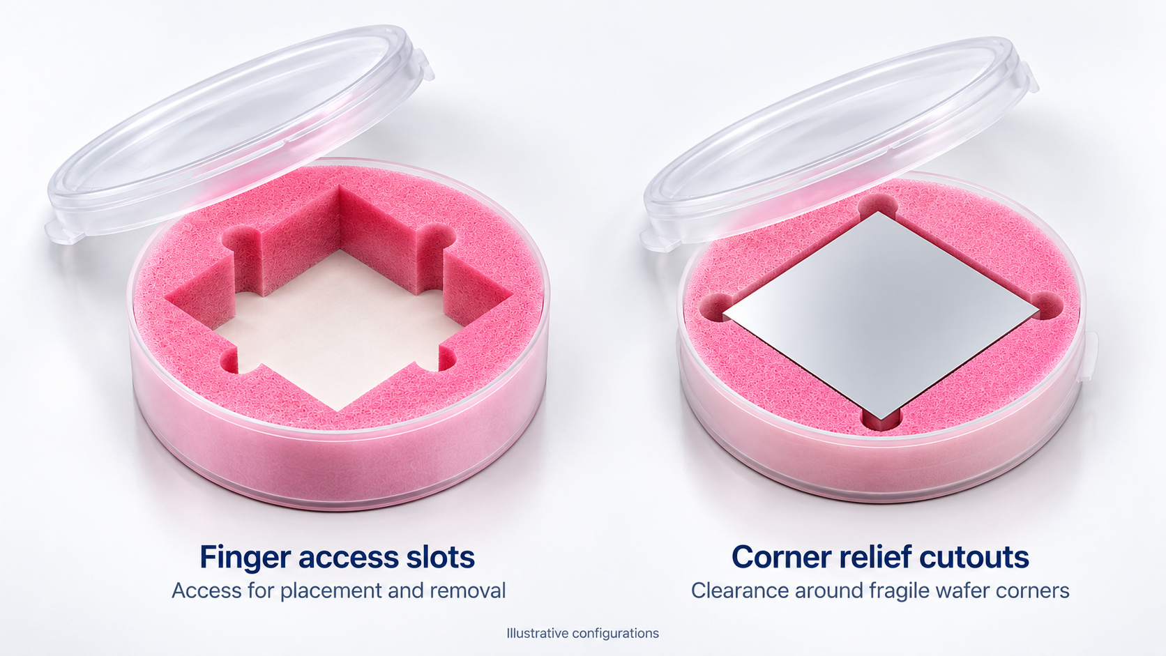
| Loading and removal | Side-centered finger-access slots can provide room for placement and extraction. Slot location and size follow the established handling method. |
| Fragile corners | Corner relief provides clearance around vulnerable tips so they can pass the foam during loading and removal. |
| Variable quantities | Review the minimum and maximum load. A partial pack may need a different cushion or spacer arrangement to maintain the intended support. |
Malaster has configured 6-inch jars for square solar wafers and other jar formats for mounted wafer frames, dicing blades and processing tools. A frame is reviewed as a complete mounted assembly, including tape and projections. A blade holder may support through the center hole while keeping the cutting edge clear. These examples describe broader customization capabilities; fit depends on the selected enclosure and insert geometry.
For a square part in a round enclosure, check its corner-to-corner dimension as well as its side length. The foam and loading clearance need additional space. A nominal wafer-family label alone does not establish the maximum square size.
The Wafer Jar Packaging Configuration guide explains the assembly and application examples. For drawing and contact requirements, see the custom foam insert specification guide.
Complete WafPak Product Systems
WafPak Product Systems combine the enclosure with specified foam liners or supports, cushion discs and wafer separators in a complete internal wafer shipping assembly. They offer a coordinated starting point when you need the packaging components together. Many sizes have both open-cell and closed-cell cushion options; the liner and supplied quantities can also differ between systems.
The following systems serve this wafer family. Compare their supplied components before selecting an option.
MC-300WCS WafPak System
Open-cell foam cushions in a PETG snap-closure shipper.
| 1 supplied | MC-300WS 300 mm PETG wafer shipper with secure snaps |
|---|---|
| 3 supplied | MC-300AFDS-1/4 12-inch diameter, 0.25-inch open-cell foam cushion disc |
| 6 supplied | MC-300TD Tyvek wafer separator |
Supplied component counts describe what comes with the assembly; they do not establish wafer capacity or prescribe a layer sequence. Review any required shielding or moisture-barrier bag, outer cushioning and shipping carton for the actual shipment.
Lined Jars and Individual Components
For replenishment or a configuration assembled from individual parts, compare MC-300TD.
Browse wafer jars and lined configurations, soft and firm wafer cushion discs and Tyvek wafer separators. Match the actual size and part number to the intended assembly. A lined jar and a complete WafPak system have different supplied contents.
Separators, Stack Height and Final Fit
A horizontal wafer pack works as a coordinated stack. In the conventional Tyvek-separated arrangement, a separator sits between each pair of wafers and between each end wafer and its foam cushion. Three wafers between two cushions therefore use four separators. Intermediate foam changes the required contact interfaces and separator count.
The separator itself contacts the wafer surface. Choose its material and outline for the permitted contact conditions. If wafer-face contact is prohibited, request a support review before selecting a stacked arrangement. The sidewall liner surrounds the stack and serves a different function from the upper and lower cushion discs.
Closed stack height = combined wafer thickness + combined separator thickness + cushion thickness under the intended compression. Include every layer and compare the result with the usable closed-lid depth. Check loading, removal and the lowest and highest intended wafer counts. Excessive compression can load a fragile wafer or prevent proper closure; an underfilled pack can allow unwanted movement.
Use the wafer packaging configuration guide to review layer order, foam selection and fit. Record the selected part numbers, quantities and packing sequence so replenishment preserves the intended configuration.
Material and ESD Considerations
This enclosure is made from PETG identified as ESD PETG. Review the required electrical behavior and supporting material documentation for your application; the material designation alone does not establish shielding or finished-package qualification. Select internal cushions and contact separators against the wafer surface and handling requirements.
Configure Your Wafer Packaging
Send Malaster the part drawing or actual outline, thickness, quantity per pack, permitted contact areas, loading method and shipping conditions. Include any approved materials, ESD or cleanliness requirements and your current packaging part numbers. We can review MC-300WC as a replacement component, a standard configuration or the starting point for a custom packaging requirement.
Discuss your wafer packaging requirements or browse WafPak Product Systems.
| Weight | 1.34 lbs |
|---|---|
| Dimensions | 13.5 × 13.5 × 3.125 in |
| Form Factor | Round |
| Material | Static Dissipative PETG |
| Wafer Product Type | Wafer Jar |
| Wafer Size | 300MM (12") |
| Product Size | 300MM (12") |
$60.150
| Quantity | Price |
|---|---|
| 0 - 5 | $60.150 |
| 6 - 20 | $54.135 |
| 21 - 35 | $48.120 |
| 36 - 50 | $42.105 |
| 51 + | $36.090 |
Please fill in the fields below with the shipping destination details in order to calculate the shipping cost.
Not sure this product is the right fit?
Share your component dimensions, drawing, or packaging requirements. Malaster can help identify a standard product or recommend a custom solution.
Explore Custom Packaging Options