
MC-76323 Conductive Tray Insert for 10mm x 10mm TQFP
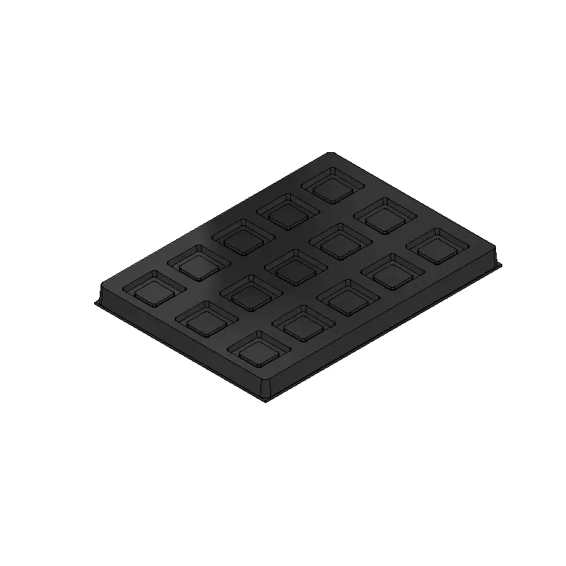
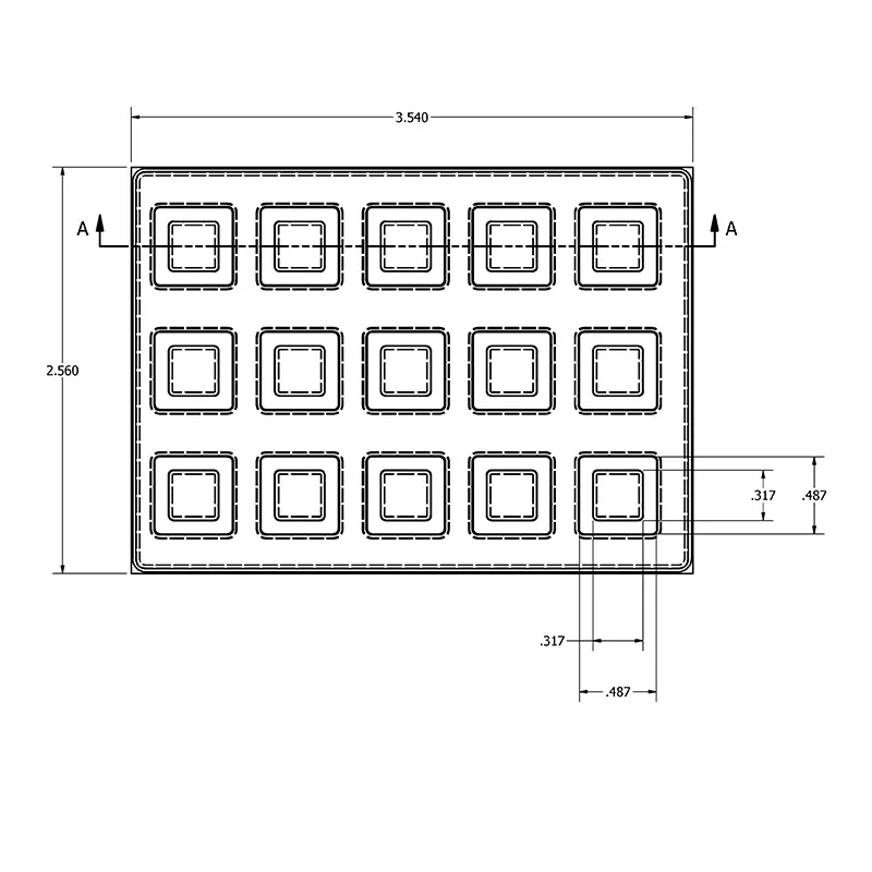
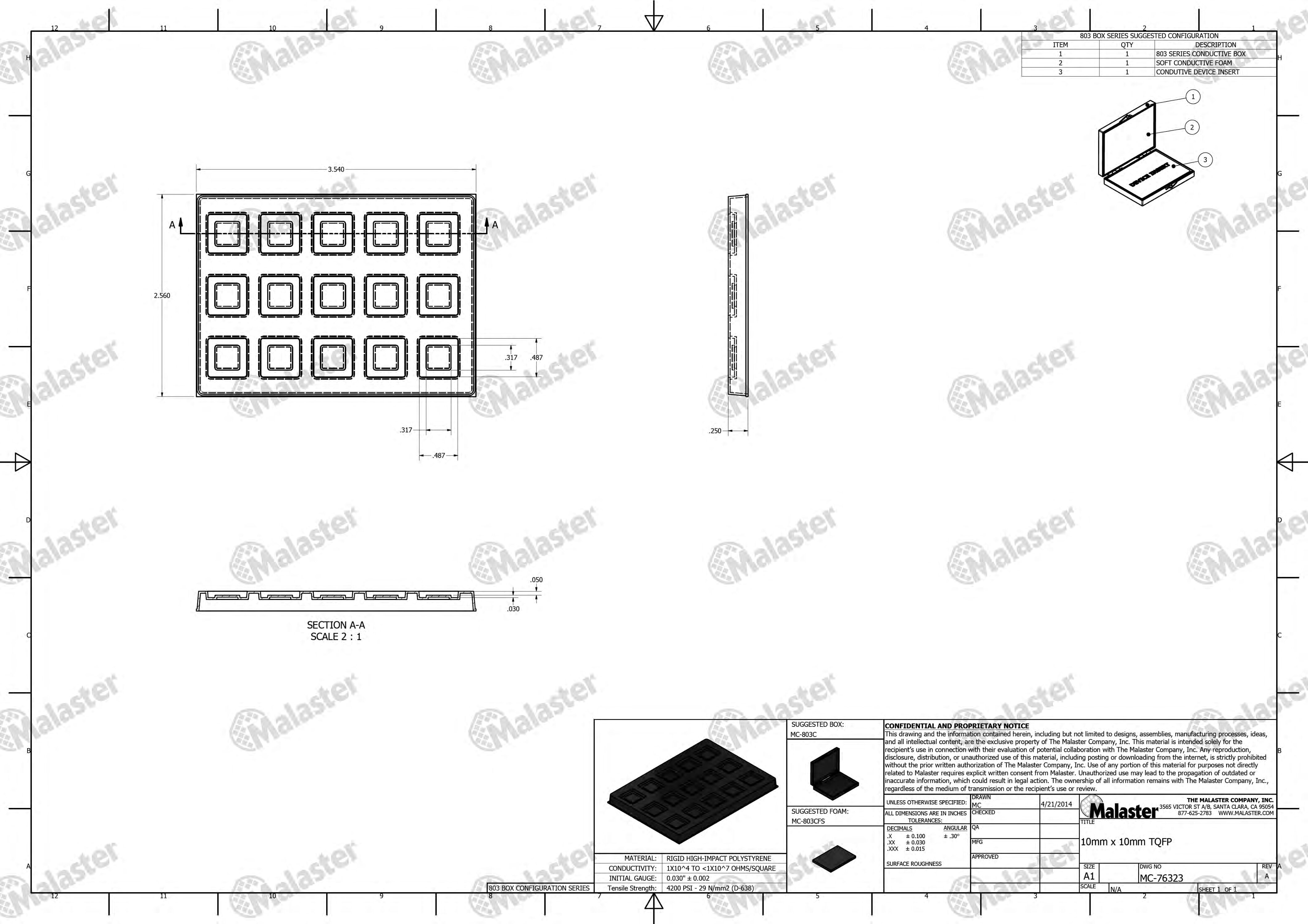
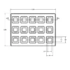
MC-76323 thermoformed conductive HIPS tray insert for the listed 10 mm × 10 mm TQFP format and 803-series box system. The catalog outline shows 15 device positions in 3 rows of 5. Specify the box and cushioning separately; confirm complete device dimensions, contact clearances and lid retention against the current drawing.
MC-76323 Conductive Tray Insert
MC-76323 Conductive Tray Insert is a black thermoformed high-impact polystyrene (HIPS) insert for the listed 10 mm × 10 mm TQFP format and Malaster’s 803-series conductive box system. The catalog outline shows 15 device positions in 3 rows of 5.
Select the insert around the complete device outline and height, including its terminals or carrier where applicable, then review the box and lid-retention arrangement. The insert, box and foam are specified separately.
Device dimensions, layout and fit
| Selection detail | MC-76323 information |
|---|---|
| Part number | MC-76323 |
| Device family | TQFP (Thin Quad Flat Package) |
| Listed device format | 10 mm × 10 mm TQFP; confirm the complete component drawing |
| Layout shown | 15 device positions, arranged in 3 rows of 5 |
| Associated box family | 803 series |
| Material and process | Black conductive HIPS, thermoformed |
| Nominal starting film | 0.030 inch (0.762 mm); finished wall thickness varies with forming |
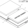
| Supplied configuration | Device insert; specify the box, cushioning and custom features separately |
Compare body dimensions, overall lead span, lead pitch and length, lead form and component height with the cavity and section views on the current drawing. Similar listed formats can differ in these details; the size or lead-count label does not define the complete external device envelope.
Component retention and packaging performance
Body and lead clearance
Confirm where the device is supported and where clearance is required. Keep fragile leads, terminals and sensitive surfaces clear of unintended contact.
Lid contact and movement
Review the insert, device and lid cushion together. The closed package should control movement without excessive loading on the component.
Loading and removal
Check orientation, finger or tool access, and removal clearance. A device that seats correctly must also be practical to load and remove in your process.
Evaluate the complete package for the intended handling, storage and transport conditions. Conductive material reference values alone do not establish finished-package shielding or application qualification. Before reuse, inspect the insert, box and cushioning for damage, contamination and changes in fit.
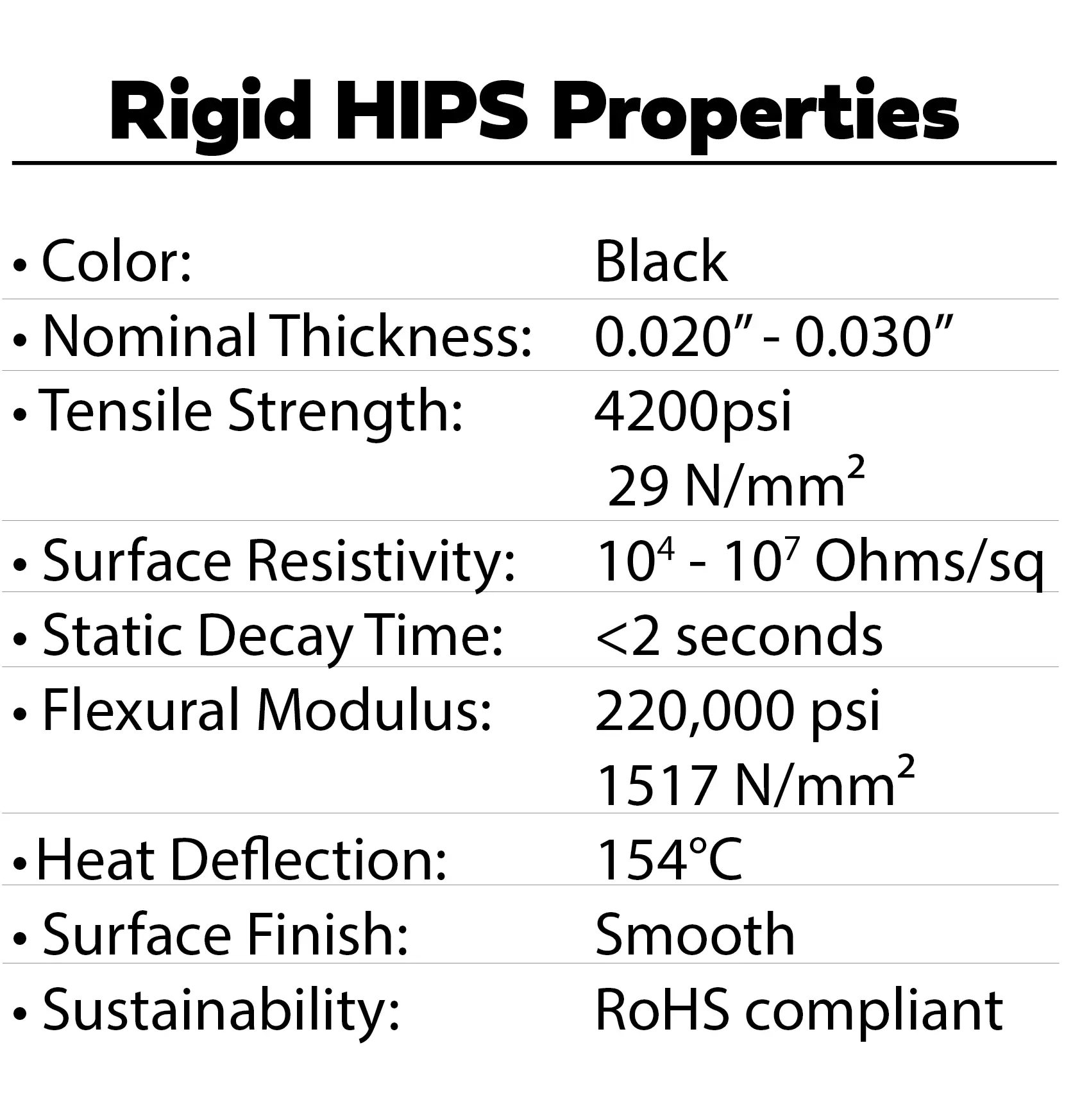
Conductive HIPS material reference properties
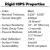
Source: Malaster MDS-HIPS-001, Rev A, released September 10, 2026. The material is black conductive HIPS film with a gloss/matte surface and a nominal starting thickness of 0.030 inch (0.762 mm).
| Property | Unformed-film reference value | Test method |
|---|---|---|
| Surface resistivity | 1 × 10⁴ ohms/square at 12% RH 1 × 10³ ohms/square at 50% RH |
ASTM D 257 |
| Surface resistance | 1 × 10³ ohms at 12% RH 1 × 10² ohms at 50% RH |
ASTM D 257 |
| Static decay | 0.10 s at 12% RH 0.02 s at 50% RH |
FTM 101C-4046 |
| Specific gravity | 1.09 | ASTM D 792 |
| Tensile strength | 3,728 psi (25.7 MPa) | ASTM D 882 |
| Cold-break temperature | -4°F (-20°C) | ASTM D 1790 |
| Heat-deflection temperature | 199°F (93°C) | ASTM D 648 |
RH means relative humidity. Static decay is measured from ±5 kV to ±50 V. Surface resistance and surface resistivity are separate properties and are reported separately above.
Starting film and finished insert
Thermoforming changes the film thickness as it takes the shape of the tool. Confirm finished wall thickness, cavity geometry and component fit against the part drawing. These are unformed-film reference values, not finished-part specifications or shipment certifications. The temperature test results are not service-temperature limits.
Material compliance and documentation
MDS-HIPS-001 reports compliance with RoHS Directive 2011/65/EU, including amendment (EU) 2015/863, and REACH Regulation (EC) No 1907/2006, based on material declarations dated February 17, 2023. It also states that lead, mercury, cadmium and hexavalent chromium are not intentionally added and their combined concentration does not exceed 100 ppm by weight.
Request the current HIPS material sheet and supporting documentation for your application or purchase specification.
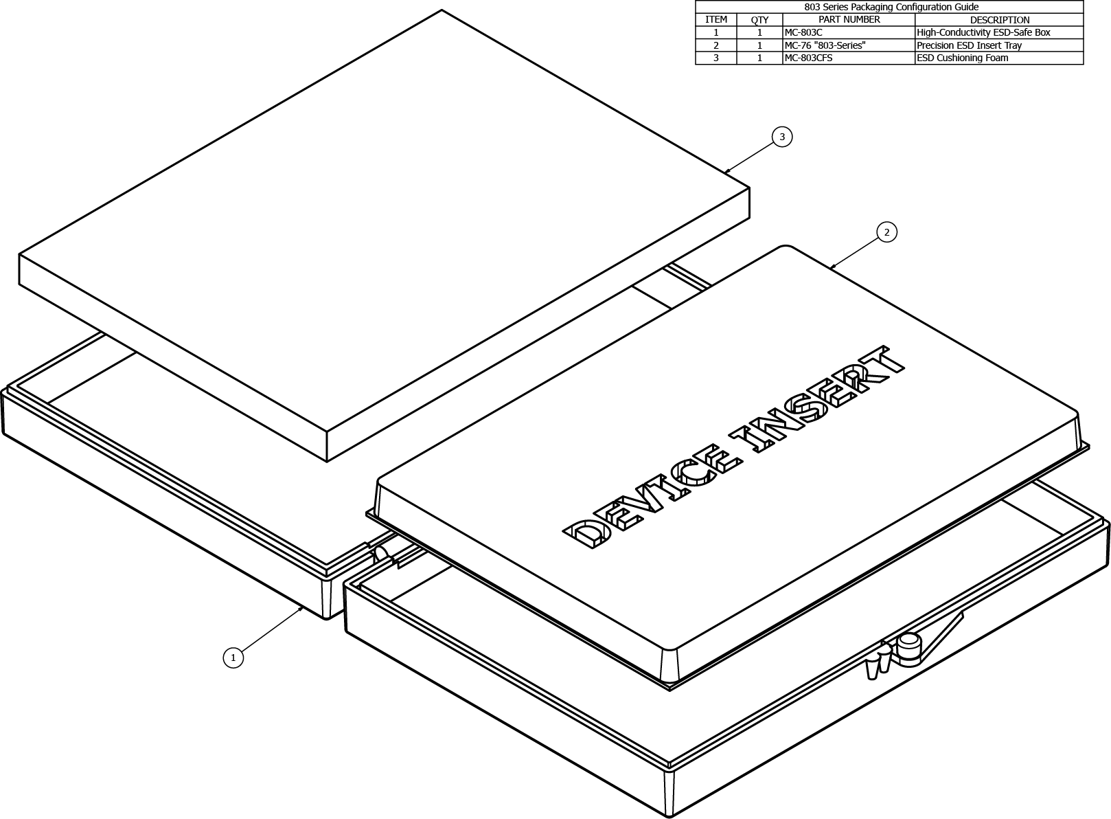
Associated 803-series boxes and package configuration
| Box | Catalog dimensions, inches | Selection note |
|---|---|---|
| MC-803C | 0.50 × 2.56 × 3.50 | 803-system box |
| MC-846C | 0.75 × 2.56 × 3.50 | Alternative listed height |
| MC-848C | 1.00 × 2.56 × 3.50 | Alternative listed height |
Start with MC-803C. Compare the taller boxes when the device and retention arrangement require a different listed height. Confirm insert seating and usable lid clearance against drawings or a sample; catalog box dimensions do not define the available internal space.
Explore conductive ESD boxes or read the ESD box selection guide.
803-series foam and retention options
These foam choices have a listed 803 footprint of 2.56 × 3.50 inches. Select the electrical function, support and compression required by the complete insert-and-box arrangement.
| Foam part | Function | Thickness |
|---|---|---|
| MC-803CFS | Soft conductive cushioning | 0.22 inch nominal |
| MC-803CFF | Firm conductive support | 0.22 inch nominal |
| MC-803AFD | Soft pink antistatic cushioning | 0.25 inch listed |
| MC-803AFDF | Firm pink antistatic support | 0.25 inch listed |
CFS and CFF are 0.22 inch nominal. Skived thickness varies; request an agreed range when clearance or compression is critical. AFD is soft pink antistatic foam; AFDF is firm pink antistatic foam.
Conductive and antistatic foams serve different functions. Review permitted contact with the component before choosing a foam or substituting one type for another. Compare antistatic and conductive foam or request a custom cushion or foam insert.
Foam alternatives for contamination-sensitive applications
For applications where foreign object debris (FOD) or particulate contamination is a critical concern, Malaster offers permanently static-dissipative cellular cushioning bonded to the box lid as a foam-free alternative. Bubble height, device contact, lid clearance and the attachment method are reviewed for the complete package. This specialty assembled option is quoted for the application.
Compare standard QFP inserts
The options below include related size or device-format listings. Compare their actual cavity geometry, layout and box family against the component drawing. A matching device-size or lead-count label does not establish interchangeability, even within the same box series.
| Insert | Listed device format | Box family |
|---|---|---|
| MC-76323 | 10 mm × 10 mm TQFP | 803 series |
| MC-76411 | 10 mm × 10 mm QFP | 1135 series |
| MC-76356 | 208-lead TQFP | 1135 series |
| MC-76232 | 20 mm × 20 mm TQFP | 1135 series |
| MC-76508 | 14 mm × 14 mm × 1.0 mm TQFP | 803 series |
Similar listings may differ in lead pitch or length, device-body thickness, terminal clearance or support geometry. Confirm the specific part drawing before substituting an insert. A change in box series also requires review of cavity layout, seating and lid retention.
Custom device-insert design and production tooling
When a standard insert does not suit the device or handling process, Malaster can develop a custom thermoformed insert and the tooling needed to produce it. Bring the component requirements into the design from the start.
Device geometry and contact
Define the body, lead envelope, sensitive surfaces and approved support areas. Review cavity depth, corner radii and the forming geometry with the tool design.
Layout and handling
Discuss cavity count, orientation, loading access and removal clearance. Include inspection, work-in-process or automated handling needs when applicable.
Box and lid retention
Develop the insert around the chosen enclosure and retention method. Options can include a lid cushion or a custom base-and-lid insert arrangement.
Tooling and production
Share initial and repeat quantities, target timing and sample-review needs. Review the proposed design, tooling scope and finished-part requirements together.
Custom work can start with a component drawing, CAD model, sample part or an existing packaging problem. Explore Malaster’s thermoformed ESD tray capabilities for larger trays, different layouts and production-handling applications.
Optional printing and product identification
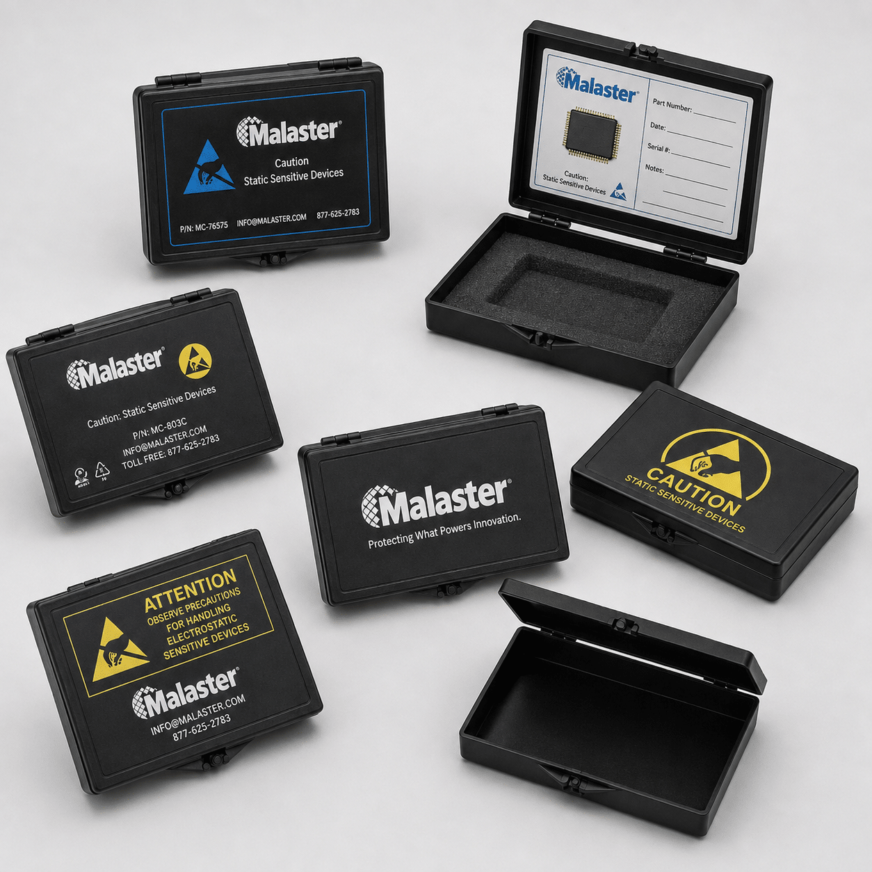
Malaster also offers custom printing on conductive device inserts. Where identification helps your process, ask about a logo, part identification or handling information.
Provide the marking content, proposed location and quantity. Review the print area alongside device-contact surfaces, clearances and handling requirements. For larger graphics or limited space on the insert, printing the associated box may be the more practical choice.
Get help selecting MC-76323 or developing a custom insert
Send the device drawing or dimensions, devices per box, planned quantities and intended handling conditions. Include lead-clearance concerns, permitted contact areas and any documentation requirements. If you are replacing an existing package, a photo and a description of the problem are useful starting points.
Malaster can help compare a standard insert, a different box system and a custom thermoformed design so the selection reflects the component and the way it will be handled.
Useful packaging and material resources
| Weight | .0125 lbs |
|---|---|
| Dimensions | .25 × 2.5 × 3.5 in |
| Box Product Type | ESD Device Insert |
| ESD Box Series | 803 |
| Material | Conductive HIPS |
| Package Style | QFP / TQFP / PQFP |
$2.350
| Quantity | Price |
|---|---|
| 0 - 99 | $2.350 |
| 100 - 249 | $2.233 |
| 250 - 499 | $2.115 |
| 500 - 999 | $1.998 |
| 1000 + | $1.763 |
Please fill in the fields below with the shipping destination details in order to calculate the shipping cost.
Not sure this product is the right fit?
Share your component dimensions, drawing, or packaging requirements. Malaster can help identify a standard product or recommend a custom solution.
Explore Custom Packaging Options